10

I would like to pump 4-5 A to a high-power LED for 100 µs. My system has only a 3.3 V battery, and this 100 µs high-power event takes place once every 10 seconds.

What is the best way of doing this without upsetting the batteries?

The answer below is very good. However, I am looking for a schematic I can use and test out.

More exact requirements:

  • Battery: Li-ion
  • Current 5 A
  • Pulse Duration: 100 µs
  • Pulse Rise time <100 ns
  • Minimum time between pulses 10 ms
  • Pulses are controlled with a 3.3 V I/O GPIO from a controller
  • The voltage drop across the LED is 3.5 V. Ideally I like to be able to put three or more in series (10.5 V voltage drop)
  • Datasheet to the LED

Bonus question

If you have a better LED recommendation with a large angle that is in the invisible range, please let me know.


I have implemented this project, and it works well except the leakage current. No matter what I tried, I couldn't get rid of the leakage. I tried a few types of opamps add a pull down resistor to the output of the opamp, etc. I end up turning off the opamp to cut the leakage. It works, but it is not very neat. I would be happy to hear what experts think of the situation.

Peter Mortensen
  • 1,676
  • 3
  • 17
  • 23
Ktc
  • 2,226
  • 3
  • 26
  • 48
  • 1
    What type of battery? – stevenvh Apr 13 '12 at 07:18
  • Just for curiosity: why do you need to pulse a high power LED for a so short time? – clabacchio Apr 13 '12 at 07:46
  • 4
    @clabacchio I will take a picture in that time.. it is an infrared flash – Ktc Apr 13 '12 at 09:20
  • @stevenvh li-ion rechargeable battery. energy capacity unknown at this time. – Ktc Apr 13 '12 at 09:21
  • Awesome! I'm also curious about how you will take the pic :) – clabacchio Apr 13 '12 at 10:01
  • @clabacchio the image sensor I am using has a LED out pin that will drive this LED. Nothing to it really. – Ktc Apr 13 '12 at 10:08
  • Do you have access to voltages higher than 3.3 V? – Telaclavo Apr 22 '12 at 10:46
  • Also, a link to the datasheet of the LED would be great. – Telaclavo Apr 22 '12 at 11:59
  • @Telaclavo, I am planning to run the system from Li-ion battery, so the answer to your voltage question is no. – Ktc Apr 22 '12 at 12:52
  • @Ktc - Can you let us know if the current answers contain enough detail? Are there more things you need in the answers? – Rocketmagnet Apr 24 '12 at 21:27
  • @Rocketmagnet the answer you have provided is not satisfactory. The problems I see are: Tolerance of inductor (in manufacturing this will be a major issue), the rise time is very long, lack of limiting resistor makes this very error prone in the field. I am looking for a very robust solution this doesn't give me the feeling of rock solid. Please correct me if I am wrong, I have noting but the desire to solve this circuit puzzle. – Ktc Apr 25 '12 at 03:51
  • @Ktc - To give a better answer, I will need to have a precise spec for: current rise time, max and min allowable current during pulse, is efficiency important, is 100Hz the maximum sustained pulse rate? – Rocketmagnet Apr 25 '12 at 08:35
  • @Rocketmagnet current rise time is per LED spec. It is in the 10ns range, we need to observe this. Max current during pulse is 5A, min is really whatever we can achieve, ideally should be close to 5A. I think efficiency is not critical at this stage. Regarding the frequency of pulses, probably it will be two very fast consecutive pulse (I am trying to build the proto to test this) 10uSec on, 80usec off , 10 usec on. Later, the next pulse train will not be another 100msec. So the duty cycle is very very l ow, but I need to turn on/off the LEDs very fast twice. (Different than my question :() – Ktc Apr 25 '12 at 09:01
  • @Ktc - 10ns rise time for 5A is *very* optimistic. Do you really *need* this? – Rocketmagnet Apr 25 '12 at 09:36
  • @Rocketmagnet Probably not. Originally, I was thinking of using a single pulse with 100usec, now I am thinking of using two pulses, 10usec each, worst case 80usec apart. That is why I am trying to squeeze the pulse rise time, but probably anything below 1usec is ok. – Ktc Apr 25 '12 at 10:02
  • @Ktcwhy do you need to squeeze the raise time? Do you have to take a so fast picture? As I see it, the rise time shouldn't affect the picture, and the fastest shutter I can imagine is some tens of microsecond – clabacchio Apr 25 '12 at 11:20
  • @clabacchio This time of rise time is needed for this application. – Ktc Apr 25 '12 at 14:05
  • @Ktc I probably lack in understanding, but you have to take an infrared picture in a 2us window, right? And why can't the flash be on for all the time? – clabacchio Apr 25 '12 at 14:10
  • @Ktc - Can you let me know about the updates I have made to my answer. – Rocketmagnet Apr 26 '12 at 20:12
  • Hey guys this is another case of the a Q not giving the end result and asking how to pump a forum. ( sorry bad pun) When I wondering where the pulse was coming from I thought it was PIC but it was 3.3V IO GPIO but Li-Ion rechargeables are 3V. Even worse GPIO is UART output and baseband IR UART is NOT the way to go. Get this [Receiver](http://search.digikey.com/us/en/products/TSOP39238CZ1/751-1389-ND/1768191) and this simple [IR Emitter](http://search.digikey.com/us/en/products/SFH%204512/475-2943-ND/2713574) you can run UART 50meters with 100mA drive to LED's instead of 5000 mA. You have not s – Tony Stewart EE75 Apr 25 '12 at 17:13

4 Answers4

12

That's an average power of

Power = 5 A \$\times\$ 10.5 V \$\times\$ 100 \$\mu\$s / 10 ms = 0.525 W.

Average power is easy for almost any battery. You just need a store to accomodate the pulse.

A capacitor that will "droop" say 0.5V in 100 \$\mu\$s needs to be

C = I \$\times\$ t / V = 5 A \$\times\$ 100 \$\mu\$s / 0.5 V= 1000 \$\mu\$F.

A supercap would do well here if voltage rating is OK.

E&OE

Telaclavo
  • 4,867
  • 19
  • 28
Russell McMahon
  • 147,325
  • 18
  • 210
  • 386
  • 4
    What is "E&OE"? :) – abdullah kahraman Apr 13 '12 at 11:52
  • 1
    Why would a supercap be better than an ordinary electrolytic? – Federico Russo Apr 13 '12 at 11:58
  • 5
    E&OE = errors and omissions excluded. (a generic disclaimer) – Adam Lawrence Apr 13 '12 at 12:53
  • 1
    As @Madmanguruman says - error and omissions excepted BUT I tend to use it only where I have been raoidly throing powers of 10 around or writing equations out of my head and may have (stupidly) put I on top rather than bottom line of an equation or missed off or added a 0 or so. ie - the principle is what matters, check my arithmetic before you depend on my answer. – Russell McMahon Apr 13 '12 at 14:13
  • 2
    @FedericoRusso - A supercap liable to have a better discharge capability for it's capacity. This may not be universally true but tends to be. – Russell McMahon Apr 13 '12 at 14:14
  • 1
    @RussellMcMahon It does tend to be true, but there are enough variations in supercaps that you must read the datasheet to be sure. Some s-caps are designed for RTC backup, with lower leakage and higher series resistance. I have seen some s-cap makers that have charts that show cap value on one axis and series resistance on the other. This makes it really easy to figure out which product line to use. –  Apr 13 '12 at 15:23
  • Any reference design I could use? – Ktc Apr 14 '12 at 02:23
  • If you could please add a reference schematic diagram of how to make this work, I like to assign the bounty to you. Thx KTC – Ktc Apr 22 '12 at 01:06
  • C is not I × V × t. It is I × t / V. I corrected that, and also the "10 s" and "4 V". – Telaclavo Apr 22 '12 at 19:44
  • 1
    @RussellMcMahon - In the power calculation, did you mean to put 10ms or 10s ? – Rocketmagnet Apr 22 '12 at 22:07
  • 1
    @Rocketmagnet I had edited that. The updated value from the OP is 10 ms. The "0.525 W" corresponds to 10 ms, if that is what you are asking. – Telaclavo Apr 22 '12 at 23:54
  • 1
    Oh right. The post actually now says 10ms and 10sec! I only noticed the 10sec one. – Rocketmagnet Apr 23 '12 at 14:14
  • Russell any chance for you to take a stab at the schematic – Ktc Apr 24 '12 at 12:18
  • 1
    @ktc - I'll try to look at it. Your slowly tightening and extending spec means it's getting more complex. || 10 uS = 1,000 shakes. A lot can happen in that time :-). – Russell McMahon Apr 25 '12 at 17:22
  • Thanks Russell. It is an experiment I am thinkering with an idea and I like to build a proto. By the time I asked the question and by the time I get answers I learn a lot which pushed me to change the question slightly. Sorry for that, at the end I am really trying to learn. – Ktc Apr 26 '12 at 00:32
  • @Ktc - Don't worry about it. I understand that sometimes a changing spec is unavoidable. – Rocketmagnet Apr 27 '12 at 08:32
10

This is the most efficient way I can think to do it. There's a MAX1682 charge pump to give you 6.6v at the super capacitor. The voltage doubler is pretty efficient, probably more then 90%, but they can't supply huge currents. But what's the average current?

5A * 100us / 10s = 0.05mA.

That's well within the MAX1682's 45mA spec.

From a brief look at the datasheet, I couldn't see any reason it wouldn't work with such a large capacitor for C2.

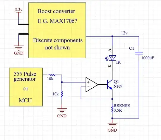
Thanks to Russell McMahon for advice about charge pump efficiency. It looks like an inductor based solution would be more efficient, but would require more components. Take a look at something like MAX17067. This also has the benefit that it can produce the higher voltage required by three LEDs in series. I'll add it to the schematic tonight.

Flash 1

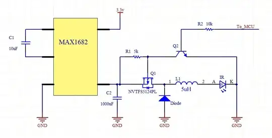
Now the important bit. You'll notice that there's no current limiting resistor. The current limiting will be performed dangerous open-loop style by the MCU. You'll have to get this right by calculation or trial and error (or both).

By supplying PWM to Q2's gate, you will be able to use the inductor as an efficient current limiter. But you won't get a very reliable current this way. It may not matter hugely, as long as 1) sufficient power is delivered to the led in 100us, and 2) the LED's current limit is not breached.

Here's a simulation I did in Altium. I used a 5uH inductor (not the 10mH shown in the schematic). And I supplied PWM with 12us on time, and 3us off time to the gate. I didn't use the 100uF capacitor, just a fixed voltage source instead. So you could expect some current droop.

Current control with inductor and PWM

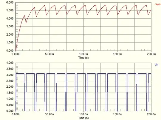
Red is the current in amps, and blue is the PWM signal. You can see that you get close to 5A within 20us, and stay pretty close to it after that.


If you want better current regulation, then you can add a sense resistor, and use it to feed back to the MOSFET.

Flash 2

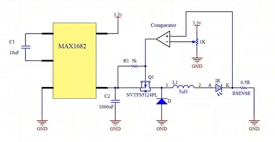
Here we have a 0.5ohm current sense resistor. At 5A, this should give us 2.5v to the comparator negative input. This is compared against the value from the pot. If the current is too high, the comparator switches off, and vice versa. The switching speed will vary depending on the hysteresis of the comparator. If the speed is too high, then you can increase the hysteresis (and decrease the switching speed) by adding a few hundred k resistor between the comparator output and its + input.

Note: You must use a high speed (<0.1us propagation delay) comparator with open drain output. You might look at the LMV7235 which is available from Farnell for about one pound.


Added:

The circuits above assume only one LED. If you still want to use 3 in series, you can use two MAX1682s to give you 13.2v.

Also, many thanks to Telaclavo for his advice on this.


Added:

OP has stated:

  • He wants a very fast rise time on the current
  • Not interested in efficiency
  • There will be a single pulse, or two pulses 80us apart, then a long pause
  • Wants a simple, robust circuit

Here is a circuit which is a linear current regulator. This is only feasible because the duty cycle is very low. This circuit will likely over-heat the transistor if the duty cycle is too large.

Flash 3

Thoughts:

  • A high voltage from the MCU or 555 will switch on the LED. A low voltage will switch it off.
  • Set the current using the voltage divider, or put in a pot so that it's adjustable. Or use a digital pot or DAC so the MCU can vary it.
  • In the schematic, the current is set to 3.3A. You can set it to whatever you want.
  • I drew only one LED, but it's meant to represent three LEDs.
  • If you use only a single LED, then set the boost regulator's output voltage lower accordingly.
  • I suggest a 555 based pulse generator for safety reasons, so it would be fairly hard to leave the current on
  • You could also make it safer by choosing a boost regulator which has a current limit. So, even if the flash is left switched on, the regulator would just limit the current anyway.
  • I cannot say what the switch on time will be. This will depend on the inductance of your wiring.
  • You should lay out the PCB carefully to avoid EMI.
Rocketmagnet
  • 26,933
  • 17
  • 92
  • 177
  • Be careful, the Q1 you drew has its source on the left (connected to C2). Real-world silicon MOSFETs have a parasitic diode that goes from S to D, so Q1 will always conduct. Even if you flip it horizontally, it will be difficult to turn it on, because none of S and D are ground. There are other issues, too. Too late here. I'll comment tomorrow. – Telaclavo Apr 23 '12 at 00:07
  • @Telaclavo - I have updated the schematics. I hope they are correct now. Please let me know what you think. – Rocketmagnet Apr 23 '12 at 09:12
  • 1) The LED cannot stand 5 A for more than 100 us. With these topologies, it is impossible to provide just a short pulse (5 A, 100 us) to the load. 2) Your 2nd schematic (the one with the comparator) does not provide a PWM signal to the PMOS. The PMOS might end up not switching, but partially on, making it dissipate too much (given the 5 A rate). 3) 5 A through RSENSE would mean 12.5 W on it. – Telaclavo Apr 23 '12 at 10:41
  • @Telaclavo - Whoops, yeah. I forgot to add a signal from the MCU in the second one. – Rocketmagnet Apr 23 '12 at 11:05
  • @Telaclavo - 12.5W on the resistor for only 0.001% of the time = 0.125mW. – Rocketmagnet Apr 23 '12 at 11:06
  • I thought you wanted to keep the buck always on (because, usually, those are not blocks that can be turned on and off very quickly). Ok, so you indeed want to provide short pulses, by powering on/off the whole buck. It might work, but the feedback needs to be very fast and accurate because, given the low value for L1 and (therefore) the high dI/dt you have at it, you may blow the LED, the inductor, or the PMOS if your feedback reacts a bit late. Also, R1 should be lower, to discharge Cgs in much less than 3 us (which is your off time). – Telaclavo Apr 23 '12 at 11:29
  • @Telaclavo - The switching frequency is only 66kHz, which is very slow for a buck regulator. It's certainly possible because I have had this working myself. – Rocketmagnet Apr 23 '12 at 11:40
  • 1
    A capacitor charging a capacitor will be relatively inefficient if the pump capacitor voltage drops by a substantial percentage during discharge or charge. (Work out 1/2CV^2 before and after discharge and be surprised). Best efficiency will be obtained with a switching regulator using an inductor. – Russell McMahon Apr 23 '12 at 16:43
  • @RussellMcMahon - Well, also if the flash rate is actually 10ms, then this puts the average current at 50mA, which is more than that MAX1682 can handle. – Rocketmagnet Apr 23 '12 at 17:05
  • @RussellMcMahon - This [charge pump calculator](http://powerelectronics.com/mag/A608spreadsht.xls) is quite interesting. If I am using it correctly, the efficiency seems to depend a great deal on the load current. I assume that's what you meant? – Rocketmagnet Apr 23 '12 at 17:16
  • 1
    @Rocketmagnet how about this Exar (http://www.exar.com/power/led-lighting/regulators/step-up-down-regulators/xrp6840/) solution with super cap? Unfortunately, the solution cannot time the pulses but perhaps that can be done with the external mosfet and secondary control mechanism. All I am proposing is inserting mosfets before the LEDs and control those mosfets based on the pulse timing. – Ktc Apr 25 '12 at 11:21
  • That solution cannot provide enough power. It's only 1.45A per LED. You wanted 5A per LED. – Rocketmagnet Apr 25 '12 at 11:47
  • @Rocketmagnet there is a version (1 channel I think) that can pump 4.5A. Assuming I can get 5.6V output, I can put two LED in series. The issue is starting and stopping it. This ic is designed in a way that you cannot stop the light. – Ktc Apr 25 '12 at 14:10
  • @Ktc - But you said you needed 5A. I am now confused about the spec. What is the actual tolerance on the current. If you can accept only 4.5A, why can't you accept a lower rise time? – Rocketmagnet Apr 25 '12 at 14:16
  • @Rocketmagnet I am not as precise you are right, 4.5A would mean lower light output, not preferred but a compromise that one could accept if the solution is robust. – Ktc Apr 26 '12 at 01:28
  • @Rocketmagnet Thanks.. You asked for feedback. I tried to simulate the circuit above without good success. However I understand the circuit, the opamp and the constant current nature of the diagram. Could you please elaborate what you mean by wiring? These are SMT LEDs. – Ktc Apr 27 '12 at 05:57
  • @Rocketmagnet I build this today on the breadboard. The circuit is extremely sensitive to the voltage on the IN+. If I touch with my hand to IN+, LED turns on. Truth is I couldn't manage to turn it off when uP is connected. Pulsing a high current turned out to be difficult. I used MCP6021 as the opamp. VN10LP from Diodes as the mosfet (I had that around, didn't use BJT). 1 ohm as RSense and the LED in question. Couldn't get it to pulse the way I wanted. (I see the pulse in IN+ but not from LED, I tried various pulse sizes, no luck) Need to look at it but it seems circuit needs more work. – Ktc Apr 27 '12 at 11:16
  • @Rocketmagnet also, if I short IN- to 5V, I see a super bright pulse. Somehow, either opamp selection or mosfet selection was not optimum is my guess. I will spend more time on monday to choose better components, perhaps try with BJT as well. – Ktc Apr 27 '12 at 11:18
  • @Ktc - I say wiring because I know next to nothing about the application. There must be some copper from the LEDs to the rest of the circuit, even if it's a PCB track. You will need to take care that this doesn't cause EMI. – Rocketmagnet Apr 27 '12 at 11:31
  • @Ktc - Are you currently using a FET? The circuit recommends a BJT. – Rocketmagnet Apr 27 '12 at 11:32
  • @Rocketmagnet this is essentially a constant current circuit. I think there is no difference between BJT and Mosfet. Either case they act as a variable resistors. – Ktc Apr 27 '12 at 11:35
  • 1
    @Ktc - The only thing is, with a FET, there are many more ways to choose the wrong one. A BJT really only needs to be NPN. Of course, the even simpler way to do this is just with a current limiting resistor. But then it might be a bit too sensitive to variation in LED forward voltage drop. – Rocketmagnet Apr 27 '12 at 11:51
3

Consider the effective series resistance (ESR) involved and loss in power transfer.

At worst case maximum input levels:

  • Surge forward current, tp = 100 μs
  • IF = 5 A Vf = 3.5 V nominal!!
  • IF = 1 A Vf = 2.0 V nominal 2.5 V maximum
  • If = 0.2 A Vf = 1.5 V nominal

Also from the LED specifications, compute ESR [mΩ]

Vf ... If[A]... . . . delta V/delta I

  • 3.5 . . . 5
  • 2.8 . . . 3 . . . 0.7/2 => 350 mΩ
  • 2.0 . . . 1 . . . 0.8/2 => 400 mΩ
  • 1.5 . . . 0.2 . . . 0.5/0.8 => 625 mΩ
  • 1.1 . . . 0.001 . . . 0.4/.2 => 2000 mΩ

(Crude estimate of ESR)

  • ESR drops dramatically as current rises.
  • You want a power source with a capacitor and switch ESR < ~10% of 350 mΩ = 35 mΩ.

Now go find a suitable low-ESR capacitor and switch total.

Maybe decouple the battery ESR with a choke to limit current within its specifications. And use suitable fusing to prevent failure of the battery.

  • These are low-ESR $0.40 switches < 15 mΩ with a 10 V drive 35 A [FDD8778CT]
  • These are low-ESR $0.40 capacitors ~7 mΩ, CAP ALUM 68 µF 16 V 20% Thru-hole
  • Pick a bigger µF value as needed.

Assuming you can manage charging Li-ion batteries choose 4x 3 V cells for 12 V across the LED and a series awitch above to ground.

You can drive with 5 V or better 12 V so the transistor can amplify 3 V out to get 12 V out to drive the MOSFET to get 5 A from three LEDS 11.5 V, with a 0.5 V drop from the 12 V Li-ion source. You ought to design the overall current limit with a ESR of the string plus an added resistor to optimize values, that is, 0.4 V drop @5 A < 100 mΩ non-wirewound resistor.

The capacitor goes across the Li-ion battery string with perhaps a microfuse and ferrite choke inserted for good practice.

Can you run the PIC from the lowest Li-ion battery in the string @ 3 V? With 3x LEDs from 12 V with a 12 V gate drive and 5 A controlled fused pulse to the LEDs.

Got the picture?

Enter image description here

Peter Mortensen
  • 1,676
  • 3
  • 17
  • 23
Tony Stewart EE75
  • 1
  • 3
  • 54
  • 182
  • The cap link is not working. Tony would you mind suggesting a circuit to do this. – Ktc Apr 25 '12 at 15:51
  • http://search.digikey.com/us/en/products/EEE-FP1E471AP/PCE4440TR-ND/1245939 Panasonic EEE-FP1E471AP – Tony Stewart EE75 Apr 25 '12 at 16:17
  • If you prefer thru hole Caps http://search.digikey.com/us/en/products/RR71C680MDN1/493-3715-ND/2207251 here is one that is 7 mΩ and in stock cheap. Use the Digikey filters to sort by ESR , Stock or price and select range of ESR, voltage and uF as desired.. lots of solutions in stock – Tony Stewart EE75 Apr 25 '12 at 16:22
  • Tony, thanks for this. However I am not advanced enough to grasp some of these without a schematic or high level block diagram. That is why I kindly asked for a circuit so that I can better discuss. – Ktc Apr 25 '12 at 16:40
  • What is overall comm channel rate and distance? Application? – Tony Stewart EE75 Apr 25 '12 at 17:27
2

A Joule thief may be the answer to your problem: it's a sort of boost converter, where you open a circuit with an inductor in series to create a high voltage. Since the power is delivered by the inductor, you don't have to supply the current directly from the battery.

You have to tune the circuit to feed the LED with the proper current when the voltage goes up.

clabacchio
  • 13,481
  • 4
  • 40
  • 80
  • 1
    Interesting.. A solution just using a Cap would be probably much more easy to manage. – Ktc Apr 13 '12 at 09:26
  • 1
    maybe, but I don't see how you would ever regulate current using just capacitors. – Jason S Apr 13 '12 at 11:06
  • @Ktc the problem is that you (presumably) have a fixed load, so the way to give it a big current is to cause a big voltage; that is the work of the Joule thief. The other chance, as Steven says, is that store the charge in a capacitor and then switch it. But depending on the LED you are using, the voltage may not be sufficient – clabacchio Apr 13 '12 at 13:01
  • A Joule Thief should work to charge a capacitor that you then discharge into three series LEDs with a constant current transistor setup to deliver the 5 amps constant current. – MicroservicesOnDDD Apr 11 '22 at 23:25