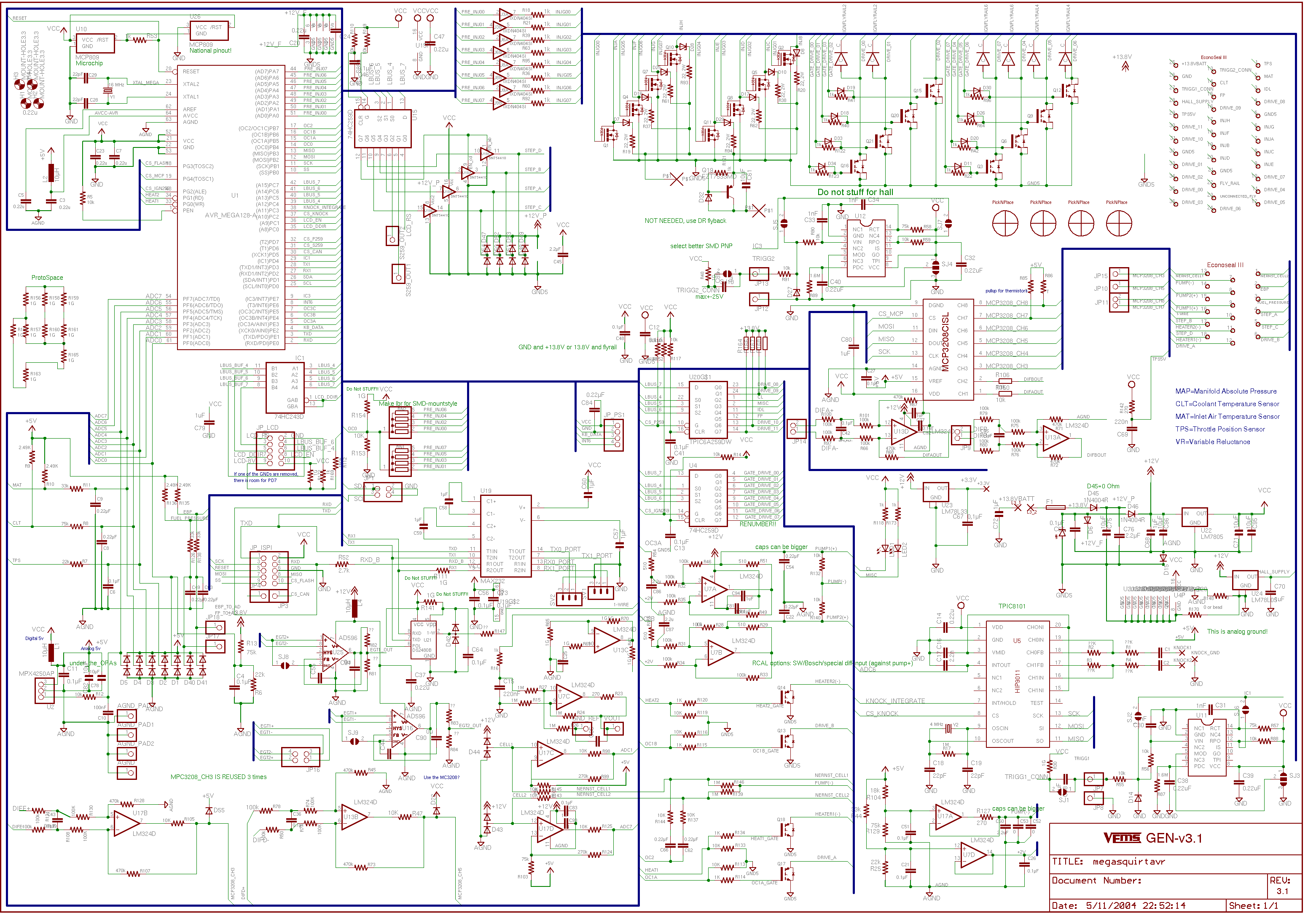
What a mess! First you need to fire whatever slob drew that schematic. Sloppiness in one area invariably means sloppiness in other areas too, which has no place in electrical engineering. You don't want this guy designing your circuits. The "eh, who cares" attitude he so clearly exhibits will cause a lot of problems.
Anyway, here is the snippet you are apparently referring to:
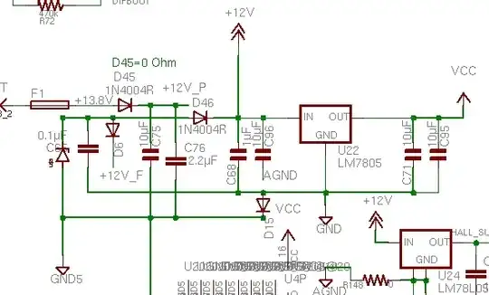
I don't see any zener diode, except maybe the one way at left. However, D46 is blocking any current from the +12V supply to it. There seems to be nothing driving the cathode side of that zener. Again this schematic is a mess and the circuit looks the same.
For a zener diode clamp to work in clipping spikes, the signal must have some impedance. I wouldn't put a zener right accross the 12V line of a car since that impedance is very low and the spikes would just fry the zener. You could put a resistor and/or inductor in series followed by a zener clamp, depending on how much current you need. However, a better way is to use a regulator intended for automotive power. National makes one, but I don't remember the model number off the top of my head. You can still preceed it with a little resistance and then a capacitor to ground. Size the resistor so that it drops maybe 2 Volts at most at your maximum current.