2

I am considering for a RFID transmitter, which just send power with no data. However, my frequency is not standard 13.56MHz not 27.12MHz, it is 27.095MHz.enter image description here Can I use the block diagram shown above? If yes, where can I get the 27.095MHz signal source?

I have two ideas now, first use a MCU and a PLL chip to derive the accurate frequency. Second, use the programmable crystal oscillator(which is also based on pll, with factory programmed) like SG8101 from epson. However, the output from SG8101 is a square wave, so I have to low pass it before it is send to amplify?

Marcus Müller
  • 88,280
  • 5
  • 131
  • 237
iouzzr
  • 349
  • 2
  • 13
  • 4
    Sounds like a good fit for a Direct Digital Synthesis IC. But you should check that your proposed transmissions are legal under the regulations of the FCC or your country's equivalent. – pericynthion Mar 30 '17 at 06:02
  • [AD9833](http://www.analog.com/media/en/technical-documentation/data-sheets/AD9833.pdf) may be suitable. – Rohat Kılıç Mar 30 '17 at 06:11
  • An oscillator employing a quartz crystal can produce a very good sine wave. But you are almost certainly talking about oscillator modules that produce square wave clock pulses. And those may be all you can get these days. – gbarry Mar 30 '17 at 08:06
  • 1
    @pericynthio 27.095 MHz is actually well-know ISM frequency. – AndrejaKo Mar 30 '17 at 08:16
  • 2
    @iouzzr Did you actually try checking 27.095 MHz for crystals? This is one of the usual frequencies for remote-controlled toys/models and you can get pre-fabricated crystals for it. It was usual for older remote controllers to have a crystal socket and you'd change channels by changing the crystal sets. The crystals sets are really cheap, so it might be worth it getting a few and experimenting with them to see what happens. – AndrejaKo Mar 30 '17 at 08:20
  • @AndrejaKo 200 watts RF though? – pericynthion Mar 30 '17 at 14:44
  • @pericynthion that's just a matter of amplification, not of the frequency standard as is – Marcus Müller Mar 31 '17 at 14:22

4 Answers4

3

How to get a high precision sine wave not available from standard crystal?

Inevitably, when transmitting power across a gap to an RFID device, to obtain best efficiency it is likely that you will make the transmit coil resonant (using a tuning capacitor) and similarly, you will make the RFID coil resonant also using a tuning capacitor.

The effect of "tuning" means that if you fed a square wave to the drive coil it would largely transmit a sine wave so, the process of producing a magnetic field will convert your square wave into a sine wave. There may be some other reasons to use extra filtering to improve the sine purity of course.

So, if you can make a square wave oscillator that runs at 27.095 MHz then your coil and tuning capacitor design should produce a reasonable sine wave. How pure this sine wave must be is down to you.

Andy aka
  • 434,556
  • 28
  • 351
  • 777
2

Filtering the output of the digital programmable oscillator you have to obtain a sine wave would be simple and accurate reliable way. I have not used your device but have used the DSC8001 programmable MEMS oscillator, which was low cost and accurate to +-10 ppm across full voltage and temperature.

For the filtering, have a look at www.ti.com/lit/an/sbfa003/sbfa003.pdf, Burr-Brown app' note 'Simple Filter Turns Square Waves Into Sine Waves'.

TonyM
  • 21,742
  • 4
  • 39
  • 62
1

To expand on Tony's and Andy's answers: Let's do a prime factorization of your frequency:

$$ 27095000\,\text{Hz} = 5419 \cdot 2^3 \cdot 5^4 \,\text{Hz}$$

Square waves have every odd multiple of their fundamental frequency as a spectral component. Now, we only have two different odd prime factors here, and we surely won't be using the 5419th harmonic (since that will practically not exist), so what you'd most likely do if digitally generating this is taking the fifth harmonic of a

$$ 5419 \cdot 2^3 \cdot 5^3 \,\text{Hz} =5419 \,\text{kHz} $$

square wave.

However, it's slightly questionable you'll find an oscillator that will readily run at a multiple of 5419 Hz, so it's not like you could simply run counter on a microcontroller.

From the top of my head, 5419 is really an awkward prime factor, since it's far from any power of 10 or 2.

You're mostly stuck with frequency synthesis by other means.

Easiest, and probably cleanest, would be having a clock synth IC that supports fractional-N synthesis with a wide range of factors. Again, it's pretty possible you'll never be able to perfectly hit your target frequency going from a common nominal oscillator frequency, but you just need to get close - nothing is perfect in this world, and an RFID system will never need atomic clock precision, or even assume a comparable short-term stability.

Another option: generate a \$5419\cdot 5^3\,\text{Hz}\$ sine (that's ca. 677.3 kHz) in software, by using sin/cos (or, depending on a lot of things, CORDICs etc) mathematically. That would mean that the period of the digitally calculated tone wouldn't have to be a (small) multiple of the clock period of your MCU. Convert to analog using some DAC (you'll need one with at least ca. 1.5 MHz sampling rate) and get the 8th overtone of that; frequency doublers can be relatively simple to build (coupling C -> diode -> simple filter).


I think the most important takeaway from your question is, however: In technologically "non-trivial" situations like these, it becomes very necessary to know one's requirements well. You didn't say what kind of frequency precision you need! I'd personally assume that something like 25ppm wouldn't be any problem, and then you'd just use a slightly different frequency with much much nicer prime factors.
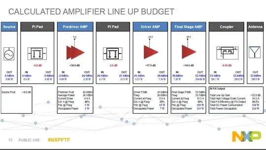
Marcus Müller
  • 88,280
  • 5
  • 131
  • 237
1

Firstly, why the fascination with sine waves?

You have a very narrow band transmit coil with lots of Q if you want reasonable efficiency and you are not doing any tricky modulation, so I would be thinking in terms of a class E power stage which will be 80+% efficient and will typically need square wave drive at twice the transmit frequency (But only cmos levels)...

A SILabs osc, 74LHC74 as the phase splitter (Use the other half to latch the thing off in the event of excess reflected power), two butch low side gate drivers, a couple of mosfets (IXYS for the fets and gate drivers would be my suggestion), some assorted R, L and C, and a hunk of 43 mix ferrite for the output transformer, job done. DC rail for the power stage would probably be designed to be about 100V or so. Enhancement mode GaN might be worth a look, but that is a whole other learning curve.

Either the SILabs part or a synth will be fine, DDS feels like overkill.

The biggest challenge in such a thing is the mosfet drivers and the cap that ensures zero voltage switching (Lots of fast current in that part).

RF power sources like this are NOT usually designed the same way you would a transmitter with modulation, they are far more like fast switch mode power converters.

Dan Mills
  • 17,266
  • 1
  • 20
  • 38