2

I have a design and layout for a buck converter which currently sits on one layer of a 2 layer PCB. I would like to force-cool the heat generating components of the board by placing them directly onto a flat heatsink.

Because there are multiple identical buck converters for different applications, having the entire board bolt to a heatsink would be ideal. I therefore wish to place the FETs on the bottom layer of the PCB. (they are SMD and not the tallest components on the board- the inductor is.

I have heard that placing the FETs on the bottom layer of the PCB (the other side to the inductor) might introduce issues into the board. Can anybody tell me if this is true, and if so, how can I mitigate these issues? Can I simply use enough vias to mitigate?

pipe
  • 13,748
  • 5
  • 42
  • 72
Chris
  • 133
  • 5
  • 1
    Yes, it is true; issues are definitely introduced. – Andy aka Mar 29 '17 at 18:05
  • @Chris what kind of issues do you think are being introduced? As written this question is very unclear and likely too broad. – DerStrom8 Mar 29 '17 at 18:06
  • Unfortunately I don't know what the issues are- could be increased capacitance affecting the inductor's designed properties? I was told the FET and inductor should be as close together as possible. How can I measure how it will be affected though? Is there a way to simulate it? – Chris Mar 29 '17 at 18:09
  • The idea of removing the heat over common housing is pretty common in aerospace designs. Just keep in mind the the inductor might have bigger losses and dissipate more power than active components. So you might need to have your heat sink properly machined to accommodate inductors, and don't forget about extra parasitic capacitance that might be added to the switchers. – Ale..chenski Mar 29 '17 at 18:11
  • Thanks Ali- We can't machine the heatsink unfortunately. I edited my question just now as it wasn't clear, but I'm talking about having the inductor on the opposite side to the FETs. Does your comment still apply in this case? – Chris Mar 29 '17 at 18:15
  • 1
    @Ali An inductor (magnetic component) can also operate at a higher temperature than semiconductors. – Nick Alexeev Mar 29 '17 at 18:15
  • @NickAlexeev, true, but due to close proximity to the switcher (as required by design), the heat might elevate the entire section of the design. So you better have the inductor beefed up, or cool it properly altogether. – Ale..chenski Mar 29 '17 at 18:20
  • @Chris, placing inductor on the opposite side is not a big deal, since all vias will be simply added to the inductance. The only drawback could be elevated emissions if you place the switching end of inductor too far from MOSFET. BTW, what kind of heat dissipation level you are dealing with? – Ale..chenski Mar 29 '17 at 18:24
  • @AliChen at max current it's 8W that needs dissipating by my calculations, but there are 8 of these, so 64W total if all the converters are at full tilt. Thermal resistance to case is 1.3 K/W or 20 K/W on top. – Chris Mar 29 '17 at 21:03

2 Answers2

1

Unless your FETs are IR DirectFETs (with metal tops) then what you propose amounts to sticking the plastic top of the FET onto the heatsink... and a thick plastic package has quite high thermal resistance.

It's better than nothing, but, well...

The way this is usually done is:

  • Put your FETs on component side
  • Put plenty of vias from the FET's back side (which conducts heat well) to transport heat to the back of the PCB
  • Make sure you have wide copper pours
  • Squeeze some Silicone Gap Filler material between the back of the PCB and a metal enclosure, heatsink, etc.

However if you got thru-hole parts with pins sticking through the board, and you don't want them to poke into the heatsink, then your gap filler is gonna be thick (unless the heat sink only covers a small part of the board) and these materials, while much better than air or plastic, still have abysmal thermal resistance compared to metal...

Also you'll need to clamp the board with an aluminium profile or something. Trying to squeeze your thermal interface material using just four screws in the corners of the board would bend it and crack your ceramic caps.

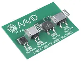
If you have airflow on top layer, you can also use some SMD heat sinks.

You won't get thermal characteristics on par with a TO220 onto a heatsink, but depending on your dissipation, it could work.

Optimize heat sink design - connect cooling pad on PCB backside by vias

enter image description here

Heatsinks at the back:

http://www.pcstats.com/articleimages/200702/Gigabyte965PDq6_m9.jpg

http://www.eevblog.com/forum/blog/eevblog-744-smd-thermal-case-design-supply-part-15/25/

bobflux
  • 70,433
  • 3
  • 83
  • 203
  • This is great, thanks. If we use all SMD devices, presumably we can mount the entire thing onto a heatsink of an appropriate size without much effort. Would you recommend thermal pads to physically separate the PCB from the heatsink? (i.e. the heatsink would be large than the entire board). – Chris Mar 29 '17 at 21:05
  • Well, you have to put something in between, and it has to handle at least the occasional bit of solder wicking into a via and making a little bulge at the back... so not too thin, and gotta be squishy too. Squishy is good, because you don't want to clamp the board too hard. Google "thermal gap filler", there are tons of those to choose from... – bobflux Mar 29 '17 at 21:20
0

There is nothing wrong with putting your power devices on the back of the board any more than any other component.

If it means extra vias etc and if the number of vias is critical then you will of course be restricted by that.

However, care should of course be taken to ensure that there are no other components on the top side of the board above the power devices.

As mentioned in another answer though, do not expect to sandwich connect the plastic side of the component to a heat-sink. In fact even the metal side of an inverted To220 type package may not make a good thermal connection. 3M does supply a line of gel-type thermal material that can however be used in such a sandwich quite effectively.

Trevor_G
  • 46,364
  • 8
  • 68
  • 151