4

Background: I did an "A" level in electronics 25 years ago; now been a professional programmer for nearly 20 years. I want to build some very basic circuits to interact with an Arduino but I've forgotten a lot, apparently :)

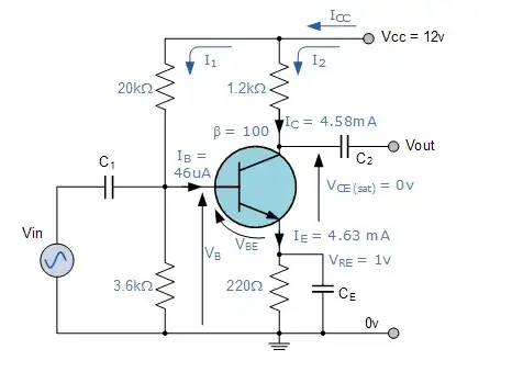
Question: I am playing around with the below circuit, and it is confusing me. The values below are taken from a website, and they work fine and as expected. However, they clip the bottom half of the waveform.

Reading that the gain is only set by RL and RE, naively, I though that biasing the transistor to half the supply would move the waveform up so that it would be amplified the same in both directions, so I altered R1 to 11k.

However, this seems to completely stop the circuit amplifying at all; in fact the gain is now ~-0.5. Now, I'm willing to accept that my change didn't do what I wanted, but if the load is only set by RL and RE, why did this have such a dramatic effect?

NOTE: I have read all the many Common Emitter questions on the site and I'm afraid the answers are a bit over my head, so if you could aim your responses at my beginner 17yo self, that'd be good :)

NOTE TWO: RE should be 470R, not 5R. Screenshot is wrong.

(Also I cannot get it to run in Circuit Lab for some reason, so here it is in PartSim - http://www.partsim.com/simulator#76064)
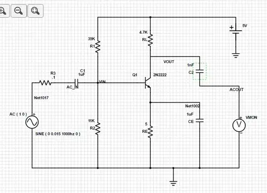
enter image description here

Whelkaholism
  • 145
  • 5
  • 1
    Try some on-line BJT bias calculator, assuming you know basic parameters. http://www.vk2zay.net/calculators/transistors/bjtBiasing.php , this gives almost identical calc as yours, except a Re is 470 ohm (beta= 50, Ic=1mA, Gv=10) – Marko Buršič Mar 28 '17 at 09:03
  • Does that value for RE really say 5 Ohms on your diagram? – Finbarr Mar 28 '17 at 09:31
  • Hmm, I'm indeed using 470R in the working circuit, must have taken the screen shot while fiddling. Will update the notes. I really want to know more about why the biasing resistors affect gain so much. – Whelkaholism Mar 28 '17 at 09:32
  • @MarkoBuršič - thanks for the calculator though, that's really helpful practically speaking. – Whelkaholism Mar 28 '17 at 09:36
  • 1
    Make sure also that the cap C2 is not really 1nF – Marko Buršič Mar 28 '17 at 10:08

2 Answers2

3

It's not so much that they affect the gain, but the fact that this change to R1 takes the transistor outside its linear operating region.

With a pair of 11K resistors for R1 and R2 you're trying to bias the base at 2.5V.

With a typical VBE of about 0.6V that means you're looking for 1.9V across RE, which in turn means an emitter current of about 4mA.

However, to get that 4mA flowing through RL to get to RE you would need to have a voltage drop of 18V across RL which you can't get anywhere near with a 5V supply.

The result is that the transistor becomes fully saturated trying to achieve that emitter current and in that state an increase in base current has very little effect on the collector current and hence very little effect on the voltage at the collector. The result is that the circuit no longer gives you the gain you want.

Finbarr
  • 5,501
  • 3
  • 19
  • 33
  • I understand most of that except the 4ma / 18V part - could you expand on how you calculate those figures please? – Whelkaholism Mar 28 '17 at 15:33
  • In linear operation, where you want to be to get the gain you're after, a small current flowing from base to emitter causes a much larger current to flow from collector to emitter. So it follows that most of the 4mA flowing out of the emitter needs to be flowing into the collector. That means that it has to flow through RL, which has a resistance of 4700 Ohms. 4mA flowing through 4700 Ohms should cause a voltage across RL of 0.004 x 4700, i.e. 18.8V. However, that's clearly impossible with a 5V supply so a large chunk of that 4mA has to come through the base causing the transistor to saturate. – Finbarr Mar 28 '17 at 16:53
  • Great, thankyou. I think the problem is I either originally knew less than I thought or I've forgotten more than I'd hoped :) Will do some reading! I've marked your answer as accepted because it was the more basic overview I was hoping for, although Marko's is very helpful too. – Whelkaholism Mar 29 '17 at 08:43
2

As user Finbarr said, it's all about defining the working region, not the amplification ratio. With wrong R1, R2 setting you go in saturation or non-conducting region.

Source : http://www.electronics-tutorials.ws/transistor/tran_2.html

enter image description here

enter image description here

Calculated example:

enter image description here enter image description here enter image description here

Marko Buršič
  • 23,562
  • 2
  • 20
  • 33