I have been working on a circuit design that would allow me to charge my iPhone/iPod classic 120 GB from my car. I am going to use power from the back of the cigar lighter sockets and put it into this circuit.
The plan is that it will step the voltage down the a usable charging voltage for the iPod. I have also had to use a voltage divider to provide power to the D+ and D- pins on the USB plug, apparently the phone will not charge with out it.
There is also an audio out section there that will basically use the GND, L Audio and R Audio and this will be wired into a 3.5 mm plug to go to my car sound system. There is also a 1 M Ohm resistor going from pin 21 on the iPod to GND to tell the iPod to shutdown when power is lost.
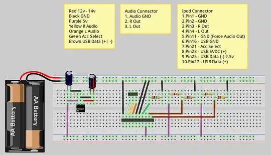
I am unable to breadboard this ATM as I don't have the voltage regulator or any rated capacitors. I have drawn up the breadboard design with Fritzing (see below). Now to the question, can anyone see any issues with my design? I am a little worried about how hot the LM7805 will get and also concerned about if the common ground is going to mess with my audio? For reference here is the iPod Pin out.
Breadboard layout
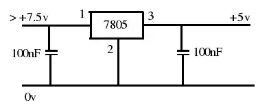
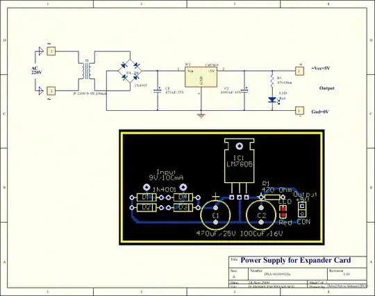
Schematic
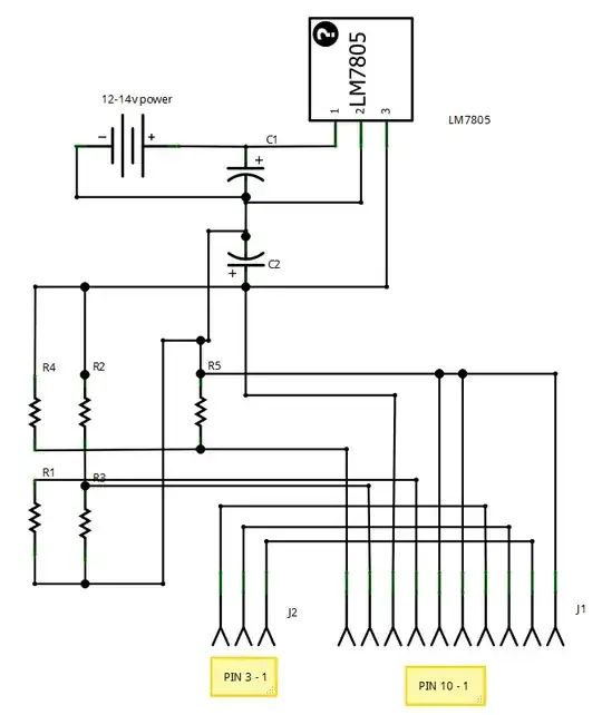
Parts list
12-14v power   Car Battery
C1             4.7uF 50V Electrolytic Capacitor
C2             0.1uF 50V Electrolytic Capacitor
J1             Generic female header - 10 pins (Ipod)
J2             Generic female header - 3 pins (Audio)
LM7805         LM7805
R1             1MΩ Resistor
R2             47kΩ Resistor
R3             47Ω Resistor
R4             150kΩ Resistor
R5             100kΩ Resistor
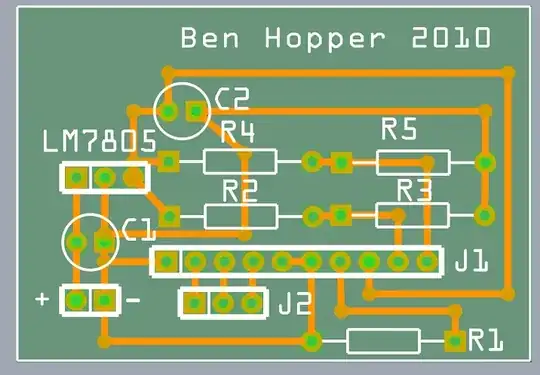
PCB layout