2

I need to build a circuit to blink an LED (about 5Hz) with a coin battery, so on 3.3V.

Main specifics:

  • Single coin battery (3.3V.)
  • The LED is an SMD5050 with 3V and 100mA maximum.
  • I would save battery as long as I can.
  • The circuit must be very small because it fit under the coin battery in a 25mm radius PCB.

How can I achieve that?

I'm thinking about a LM555 in SMD package.

JRE
  • 67,678
  • 8
  • 104
  • 179
Noisemaker
  • 603
  • 1
  • 14
  • 25
  • 8
    Small microcontrollers these days run from microamps or less if you configure them correctly - so that requirement of your doesn't make sense. – brhans Mar 23 '17 at 20:30
  • 2
    5hz doesn't really tell you the duty cycle, how long do you want the LED to remain on during each on cycle? For example if you have the LED blinking 1ms every 199ms, that is only a 0.5% duty cycle. If you have it on for 100ms and off for 100ms, that is a 50% duty cycle. 100mA is a lot to ask of a coin battery... Is size a problem? You can get very small Lithium batteries that may handle the current better. – Ron Beyer Mar 23 '17 at 20:34
  • Swithing a 3.0V LED from a 3.3V battery leaves almost no available switching headroom. Remember a PN junction has about 0.7V drop. You may be able to achieve near 0.3V Vce drop if you drive a NPN to saturation, but that will take more power. Can you use a higher voltage (like 2 coin cells in series) or use a lower-voltage red LED? – MarkU Mar 23 '17 at 20:47
  • No I need a single 3.3V coin. The circuit must be very simple because it need to fit in just below the coin battery, so inside a 25mm circular PCB. – Noisemaker Mar 23 '17 at 21:21
  • @Noisemaker microcontrollers can be small enough to fit in that space. As brhans says, why not use it as they achieve your low power requirements. Take for example the attiny13a – Bradman175 Mar 23 '17 at 21:25
  • Yup a micro is your ideal choice... very limited external components... if any. – Trevor_G Mar 23 '17 at 21:26
  • The minimum supply for a LM555 is 4.5V and its current when its output is turned off is 6mA. An LMC555 works at 3.3V and down to 1.5V with a very low idle current but its output current is too low, it needs an external output transistor to drive an LED. if you set the LMC555 to produce pulses that are 30ms long then the LED will appear at full brightness. Less than 30ms appears dimmed. – Audioguru Dec 22 '20 at 00:11

6 Answers6

4

While you could buy a blinking LED as suggested, you are then constrained to the blink rate provided by the supplier.

I'd suggest that the cheapest and most flexible solution overall would be something like an ATTiny13A in an 8 pin SOIC. Your 5050 LED (If it's RED) has a Vf of about 2.2 V @ 100 mA, so you will need a series resistor to limit the current (a 12 Ohm resistor).

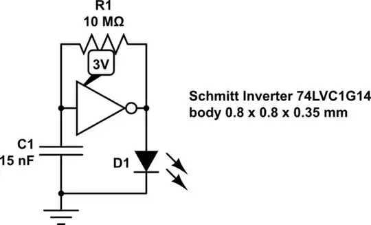
You could (once it's programmed) use 5 of the ATTiny13 pins in parallel to drive the LED with a 100 mA pulse (to ground) and have one pin left (Reset*) to provide an on/off switch/jumper capability.
You could have a single power supply decoupling capacitor, but at very low frequency (I'd run the ATTiny at 128 kHz) it's doubtful you need it. You be able to disable all features in the ATTiny and use the Watchdog Timer to bring you out of power down mode 5 times a second (you'd actually have to wake up the MCU every 4 mS and count to get your 200 mS time). Once awake you can time the pulse width of your LED drive using a timer or register (not much difference in this application).

An ATTIny13 is about $0.60 1 off, a 555 timer about $0.48, but you'd need two to provide 5Hz and then your pulse width for the LED on time ....so the MCU is by far cheaper. If you are only building a few of these items, the ATTiny85 would be the best choice for ease of programming (direct from the Arduino IDE),though it'll cost you about $1

Getting 100 mA from a CR2032. The short answer is that you can't, but you can put a capacitor across the battery and use this to store energy for a larger pulse capability.
This limitation and solution below apply whether you use 2 * 555 or an MCU solution.
The CR2032 does have some useful pulse capability, and probably more than you would think: enter image description here This tells us that the output resistance of the battery is about 10 Ohms and that with a 100 Ohm load you'd easily get a short pulse capability of about 29 mA.

The capacitor is charged to the battery terminal voltage and we know that if we have a load of 100 mA that while drawing that current both the battery and the capacitor would supply it. When the voltage drops down to 2.9 V we know that the battery is supplying 29 mA maximum, so the rest must be coming from the capacitor, 71 mA. Since the battery supplies no current initially and 29 mA @ 2.9 V, then we can average the current from the capacitor at 86 mA.

A very approximate calculation would be to consider the load a constant current on the capacitor (it isn't, but it simplifies our calculations) and use:
t = {C x (V0 - V1)} / I
We can use this to find the maximum LED on time that could be supported once we select the maximum capacitance that fits in the form factor.
Since the solution is probably disposable, we need to use small cheap capacitors that will fit within the battery diameter and not be too high. Ceramic and Tantalum capacitors would be too expensive, leaving us with Aluminum Electrolytics.
A reasonable choice might be 2 * 470 uF 4 V Nichicon low leakage, low height capacitors. At 8*5 mm two of them will fit within the battery diameter ...so this might work as an example.

So with 2 * 470 uf and a constant current of 86 mA what is the pulse width that could be driven?

t = (940 * 10^-6 * 0.3) / 86 * 10^-3 = 3.3 mS

And of course if you were to drop the LED pulse current to say 50 mA, you could drive a much longer pulse width or drop one of the capacitors.

t = (940 * 10^-6 * 0.3) / 35 * 10^-3 = 8 mS

The only element we have no details on is the short pulse battery recovery time. This may limit the flash rate, so you'd have to actually try it out on a coin cell battery to see if you can achieve 5 Hz.

Hope this helps.

Jack Creasey
  • 21,428
  • 2
  • 15
  • 29
  • I found a 5050 led, with lower current (around 20mA) and goog luminosity. It seems good for my purpose because I don't need so very bright light, due it will be used without sunlight. It should be easier with lower current, right? – Noisemaker Mar 25 '17 at 10:29
  • Very much so, if your peak current is going to be 20 mA (still close to the peak the battery can comfortably deliver) you could use just a 220 uF cap and get 5 mS pulses with only a 0.2 V drop. – Jack Creasey Mar 25 '17 at 17:07
3

schematic

simulate this circuit – Schematic created using CircuitLab

Any LED current is limited by Coin cell ESR to about 10mA and stays bright for a day and faint for a month.

An old photo of mine below. enter image description here

Tony Stewart EE75
  • 1
  • 3
  • 54
  • 182
2

You can connect a LED directly across a coin cell. The internal resistance of a coin cell is high enough that it will limit the current by itself.

Since a coin cell will never, EVER, be able to deliver 100mA into a LED..... you'll be lucky to get 5-10mA........ don't worry about burning your LED. Don't worry about the driver either. Any microcontroller or logic chip will have the 5mA drive current you want on any of its output. If you wanted higher drive current, you wouldn't be using a coin cell!...

Now, the blinking. Since your LED will use most of the cell's energy anyway, you don't need ultralow power hardware. A PIC12 or other low pin count, dirt cheap microcontroller will do the job just fine on a every low idle current, which will be negligible compared to the LED current draw.

bobflux
  • 70,433
  • 3
  • 83
  • 203
1

You can use an LMC555/TLC555 or a microcontroller. The latter will be simpler and probably cheaper. The LMC555 is available in a fairly compact 1.5 x 1.5mm BGA package but requires more external components.

You can only realistically get a few mA from a coin cell battery, which is just as well as you need to have the LED Vf very low. Modern LEDs can produce a fair bit of light with 0.5-2mA.

The maximum rated LED current does not matter (within reason) in this application, look at the luminosity at (say) 1mA and pick one that is bright at low current. If you don't have proper datasheets that contain that data, do your own testing or pick on that does have a proper datasheet (preferred).

Spehro Pefhany
  • 376,485
  • 21
  • 320
  • 842
0
  1. Use a blinking led. Or

2 build an avalanche oscillator. They rely on reverse break down of a pn junction.

dannyf
  • 4,272
  • 1
  • 7
  • 9
0

100mA LED is problematic

The blinkers available from TI, Linear, and NXP only drive 20-30mA LEDs.

So it looks like the 555 or micro is not a bad option.


Battery is problematic.

Except you 100mA LED is going to kill it. Most coin cells are 3.0V. To get a 1000mAh 3.3-3.7 is going to be $5+.


3V forward voltage is problematic

A red, orange, or yellow LED will have a lower forward voltage and therefore will disable less wattage.


I know there is a perfect circuit for this, I just do not know where it is.

This is exactly what you want.

This LED blinker was on the packaging of a Logitech mouse I purchased years ago.
The blinker circuitry is under the black blob.

So blinkers do exist it's just a matter of finding one.
I search the numbers, closest I got was someones license plate number.

enter image description here


Or the easy way, blinking LED

The blinking LEDs at Digikey

enter image description here

Passerby
  • 72,580
  • 7
  • 90
  • 202
Misunderstood
  • 7,287
  • 1
  • 11
  • 24
  • LOL. I ripped that apart too. Ancient history. Continuous blinking on the box. It ran off some nice Duracell alkaline AA cells, if I recall correctly, which I repurposed. – Spehro Pefhany Dec 21 '20 at 21:09