3

We are contemplating a design which will need 2 PCBAs and be potted. One board is quite "special" so it's rather impractical to reduce the design to a single PCBA.

The conventional wisdom is that soldered wires should be used as conventional board-to-board connectors such as FFCs or pins headers will be unreliable in a potted design.

What other techniques can be used for board-to-board connections in a potted design? In this instance, there would be 10 lines, two of which will be 12Mbps USB (no genuine high-speed signals). Of course, soldering wires is still possible in this design, but time consuming and possibly error prone in production.
Damien
  • 1,504
  • 1
  • 17
  • 30
  • Excuse my ignorance, what does "potted" mean in this context? – Jonas Schäfer Mar 22 '17 at 08:39
  • 3
    Potted - Circuit assembly that is encapsulated in some type of compound - epoxy is commonly used. Often there is a open sided container into which the circuit assembly is inserted and then the potting compound is poured into the container to cover the electronics. – Michael Karas Mar 22 '17 at 08:55
  • 1
    @JonasWielicki, I have added a link to the relevant wik page. – Damien Mar 22 '17 at 22:52
  • 1
    Thank you very much! I should really start to try Wikipedia when dictionaries don’t make sense to me. – Jonas Schäfer Mar 23 '17 at 07:19

2 Answers2

1

Solder wires

There is little evidence that soldered wires are any more "time consuming or error prone" in potted PCBA at the scale of just 10 connections.

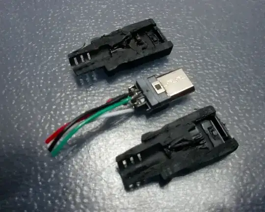
The traditional causes of failure with unterminated wire connections are mechanical in nature and resolved by the additional stability that potting applies. In fact, most connector systems (including USB) feature similar construction inside their cable assemblies (connector -> miniature PCB -> wires -> mini-PCB -> connector)

Here, the overmolding of the cable is performing the same job that the potting will in your PCBA

enter image description here

DrFriedParts
  • 12,482
  • 36
  • 54
  • Isn't there a risk that the potting may come between the two connectors' metal parts and as such isolate the connector from making a reliable connection? – Araho Mar 22 '17 at 08:21
  • @Araho -- There is no connector with direct soldering... that's why it's the commonly used technique. – DrFriedParts Mar 22 '17 at 10:06
  • Oh, so what you're saying is that he should solder wires from PCB to PCB, right! I somehow saw your picture and misread, thinking you meant that he should solder _connectors with wires_. My bad! – Araho Mar 22 '17 at 10:51
1

Potting connectorised boards usually does just fine, and is a very, very common thing in the marine electronics game.

If a connector is going to have reasonable reliability in air, it must make a gas tight joint at least over some of the mating surface area, so why would potting be a problem?

Now obviously one should not use utter junk, but by the time you are looking at anything decent it should be a non issue.

Mind you, for 10 wires I would be looking at buying a solder in preformed ribbon of appropriate pitch, hard to get that wrong, and probably cheaper then a connector pair.

Dan Mills
  • 17,266
  • 1
  • 20
  • 38
  • He's talking about non-bulkhead, non-sealed connectors (FFC, rectangular pin headers, et al.). The connectors you are describing are application specific, sealed, and, even so, are usually pigtail-bulkhead connected to the main board (e.g. direct wire-soldered at the PCBA side) – DrFriedParts Mar 22 '17 at 12:02
  • So was I, bulkhead mounts are a different animal and are generally fine as well of course (Make sure you get ones that are still sealed when unmated!), but I was thinking the usual sorts of Samtec/Molex/Amp board to board stuff, not the expensive wet mate parts. – Dan Mills Mar 22 '17 at 13:17
  • @DanMills, are you please able to provide some example parts? This will help reduce the confusion as to what types of parts you have had success with. – Damien Mar 22 '17 at 22:53