This question made me wonder. Say I want to drive a LED when a small level audio signal is present. I understand how to do this with an opamp, but how about a transistor. You'd have to bias it so that it just doesn't conduct without the signal, so that any extra voltage on the base will cause collector current to flow, right? Can anybody please explain how you do that: bias the transistor so that it just doesn't conduct, independent of temperature variations and such? Or is this the wrong approach?
Asked
Active
Viewed 2,110 times
2 Answers
5
You're probably thinking of the common emitter circuit which is typically used for a switching transistor, i.e. with the emitter directly to ground. This is OK for switching, where two extreme states occur: one where there's no base current (base voltage is 0V) and one where there's a set base current of several mA to saturate the transistor.
Now suppose you place a resistor between the emitter and ground, R2 in the schematic below:
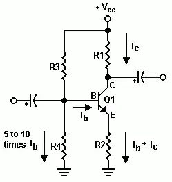
This resistor provides negative feedback, which stabilizes the circuit. A small increase in base current, for instance because of temperature changes, will cause a large change in base voltage. That's because the extra base current isn't the only current flowing through R2, there's also \$I_C\$, which is \$H_{FE}\$ larger than \$I_B\$. This higher current will cause a large voltage drop across R2, in turn causing the base voltage to increase by the same amount.
Example: R2 = 10\$\Omega\$, \$H_{FE}\$ = 100, \$I_B\$ = 1mA. Then
\$ V_E = R2 \times (I_B + I_C) = 10\Omega \times (1mA + 100mA) = 1.01V \$
If for some reason the base current would rise by just 10\$\mu\$A, then
\$ V_E = R2 \times (I_B + I_C) = 10\Omega \times (1.01mA + 101mA) = 1.02V \$
so the base voltage will also rise by 10mV, which would counteract the current rise. This effect will be stronger when R2 is larger.
edit
Now place a capacitor parallel to R2. That means that the impedance between emitter and ground is (much) lower than R2 for AC signals. So for AC the negative feedback is not as high, and the signal will be properly amplified, while the DC setting remains stable.
stevenvh
- 145,145
- 21
- 455
- 667
-
I think he is not asking about this. What he asks is that it will not conduct when there is no signal present, and will not be affected from temperature variations and such, so no matter what temperature is, it will stay off when there is no signal present. I think he wants to create a comparator with a transistor. What he means with the bias is; the bias will be at some point that without the signal, the transistor will be off, and adding the signal to the bias will turn the transistor on. – abdullah kahraman Apr 06 '12 at 17:27
-
@abdullah - added a paragraph (and a capacitor) – stevenvh Apr 06 '12 at 17:35
-
Yes, but you still have 1mA of base current. How about zero? – Federico Russo Apr 06 '12 at 17:52
-
@Federico - at zero current you wouldn't have a voltage drop across R2, but if your R2 is very large say 10k\$\Omega\$ you'll get a voltage drop of 1V for only 1\$\mu\$A input current. – stevenvh Apr 06 '12 at 17:57
-
@Federico - Actually, the output is AC coupled. So, the DC output will be zero even the transistor is biased and is ON. As soon as there is an AC input in the base through the base capacitor, there will be an AC output at the collector capacitor. So, no signal, no out. The only output when there is no signal is going to be there at the power-up if the collector capacitor is not charged. There will be no more output after the capacitor is charged after power-up, which will be depended on R1, C1 and \$C_L\$, \$R_L\$ – abdullah kahraman Apr 07 '12 at 05:37
1
What you ask is doable. Here is a circuit that should work, although I haven't tried it:
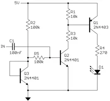
Q2 is biased just short of turning on. This is done by putting a little bit of current thru Q3 and using the resulting base voltage to bias Q2. This bias is additionally fed thru R5 so that the voltage on the base of Q2 will be a little lower if it does try to draw current. It also isolates the low impedance of the voltage source formed by Q3 from the audio signal. Since Q3 and Q2 are the same transistor type, they should have similar enough characteristics, including B-E voltage over temperature. This makes the biasing of Q2 reasonably immune to temperature changes.
When Q2 turns on, it will turn on Q1, which turns on the LED. Q1 adds more gain to the circuit so that a weak audio signal can eventually drive 10 mA thru the LED. R3 limits the base current of Q1 so that Q2 can saturate with no harm, as it will at the peaks of a reasonable audio signal. There will be about 420 µA thru R3 when Q2 is fully on. R1 is there to require some minimum current to turn on Q1 which might be necessary as Q2 is biased right at the edge of significant conduction. R1 will draw about 60 µA, leaving 360 µA thru the base of Q1 when Q2 is fully on. The LED will require up to 10 mA of collector current thru Q1, so this means Q1 must have a gain of at least 28, which is well within the capability of most small signal low voltage PNP transistors. You want Q1 to have some extra gain so that the LED will be fully on even when Q2 is only partially on.
C1 AC couples the audio input and prevents it from messing up the DC bias of Q2.
Olin Lathrop
- 310,974
- 36
- 428
- 915
-
Thanks. Is there a difference between just using the B-E junction of Q3, and tying base and collector together like you did? – Federico Russo Apr 07 '12 at 13:21
-
And would it help to use a double transistor for Q2/Q3? I'm thinking about better matching and thermally connected. – Federico Russo Apr 07 '12 at 13:23
-
1@Federico: By trying B and C of Q3 together, you get the base voltage *that causes the desired collector current*, which in this case is the current coming thru R2. A truly matched pair would give better performance over temperature, but if you care about that level of accuracy then you should be using a comparator with precision parts, not something like this circuit that doesn't have a precise threshold. – Olin Lathrop Apr 07 '12 at 13:33