1

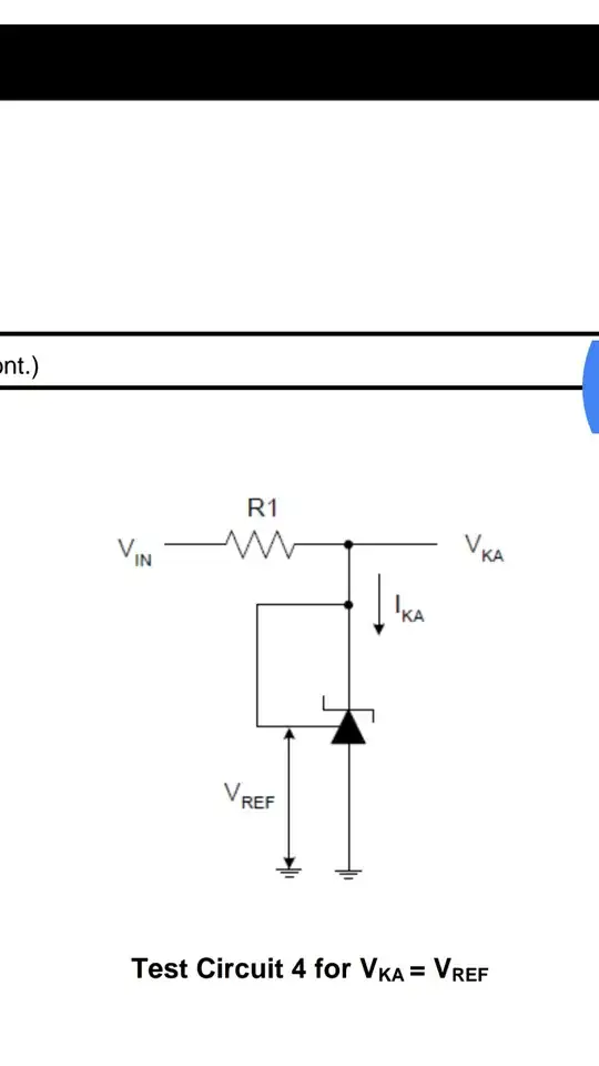
Below is the circuit for constant voltage. The Value of R1 is 330 ohm and when Vin = 3.6V , the Vka = 1.5V And when Vin changes the value for Vka also changes. it should be stable

Why? The Vka should be equal to 2.5V

enter image description here

MICRO
  • 510
  • 4
  • 25
  • 1
    Show the complete circuit, and tell use the voltages you're using. – CL. Mar 21 '17 at 12:22
  • "Test Circuit 4 for VKA = VREF" and VREF is defined to around 2.5V so clearly you are not giving it enough headroom to regulate with your 3.6V – PlasmaHH Mar 21 '17 at 12:32
  • The configuration in your question forces the TL431 to act like a 2.5V zener diode. According to the datasheet, input voltage can be anything between 2.5V and 36V so there's no problem in your circuit. But your bias current is too high *(around 3mA but it should be 1mA max)*, this shouldn't be the cause though. Maybe you can place a higher resistor like (3.6V-2.5V)/0.5mA = 2k. – Rohat Kılıç Mar 21 '17 at 13:39
  • 1
    @RohatKılıç: The TL431 needs 1mA *minimum*, not 1mA max. It won't regulate properly below 1mA. Also, this is not a "zener diode," it's a shunt regulator with much better performance than a zener diode. The configuration as shown is correct, and I believe the values given are all correct, which means the OP is leaving out some important fact that explains the problem. – Warren Young Mar 21 '17 at 13:45
  • Do you have a load on this circuit, or is it being tested unloaded? With a shunt regulator, the proper resistor value [depends on the load](http://electronics.stackexchange.com/questions/5213/does-the-tl431-have-a-dropout-voltage-per-se). – Warren Young Mar 21 '17 at 13:49
  • @WarrenYoung I know what the TL431 is. But the config above forces it to operate "like" a zener diode. About the bias current, yes, it should be "minimum". Datasheet states that typically 0.4mA to 1mA "minimum" is enough. In most SMPS circuits I designed, I stay between 0.5mA to 1mA with no problems. – Rohat Kılıç Mar 21 '17 at 13:51

0 Answers0