5

Rookie circuit-bending question: I am trying to hack a walkie-talkie to light up some LEDs when it receives a signal. I figured the easiest thing to do would be to have the LEDs light in relation to the audio signal, but I don't want to compromise the sound quality too much.

Someone on another forum suggested the following:

circuit diagram

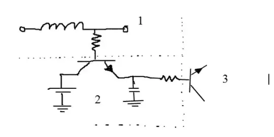
Some explanation: 1: This is the speaker, just hook up the transistor to one of the ends of it. If one end doesn't work, try the other.

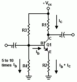
2:The transistor will be triggered by the voltage on the speaker, and charge up the capacitor. The capacitor will retain it's charge for some time while triggering the Transistor in 3. Then you can hook up whatever you want to the transistor, like an LED. You might want to use a darlington transistor (just 2 transistors cascaded like this: http://i56.tinypic.com/5nm683.png ).

You will have to play around with the values for the capacitor and the right resistor, but something along the uF range and 1-10 kOhm should do the trick. The resistor on the transistor at 1 should be rather more than less if you don't want to impact the sound quality too much, so also something along the 10 kOhm range.

I tried this out, but no luck.

EDIT: I tested the + to - leads on the speaker. When it is making a sound, it goes up to about 30V AC.

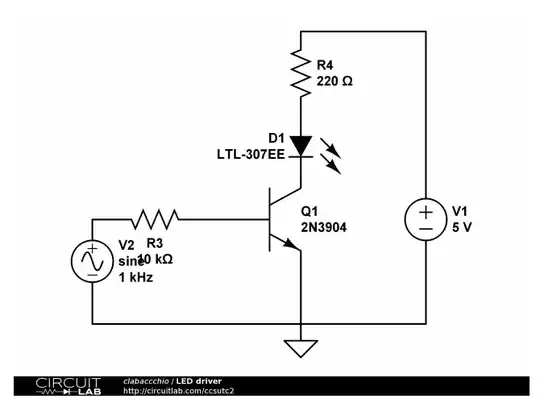
I also tried variations on the circuit below.

enter image description here

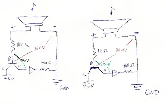
It is not lighting up the LED.

I read on this Transistor Circuits page that transistors require .7V between B and E to switch on. As shown in the color sketch, the voltage measured is much lower than that.

I'm not sure where to go from here. I assume I just need to increase the voltage between B and E on the transistor, but how?

Mike Eng
  • 225
  • 3
  • 7
  • 1
    I think it's time to have your hands on an electronics CAD tool. Check out [KiCad](http://kicad.sourceforge.net/wiki/Downloads). – abdullah kahraman Apr 05 '12 at 06:45
  • 1
    Yep, once you show your schematic to someone else it's long past time to put your hands on a CAD tool. KiCAD is a great program, and I recommend many of the other apps in our [Good Tools for Drawing Schematics](http://electronics.stackexchange.com/questions/1024/good-tools-for-drawing-schematics) list, but I've recently become enamored with [CircuitLab](https://www.circuitlab.com/), which is probably the best option if you want to edit your schematics online. – Kevin Vermeer Apr 05 '12 at 22:32
  • 1
    Great to see designers drawing circuit diagrams. Look at that note above the speaker lol – abdullah kahraman Apr 06 '12 at 09:14
  • What is the code of the transistor you are using? – abdullah kahraman Apr 06 '12 at 09:15
  • 3
    A walkie-talkie with 30V over the speaker? What kind of power supply does that have? – Federico Russo Apr 06 '12 at 14:39
  • @abdullah kahraman - here is the transistor I used: https://www.jameco.com/webapp/wcs/stores/servlet/ProductDisplay?langId=-1&storeId=10001&productId=38359&catalogId=10001&krypto=9x3mj8umRTodJUQbzqkANINX%2BjjVZG3eIE0yx%2BqqWQh9PVQnC6vJUA%3D%3D&ddkey=https:StoreCatalogDrillDownView – Mike Eng Apr 09 '12 at 03:46
  • @federico russo - the walkie talkie runs on three AAA batteries. I discovered that one circuit utilizes all three batteries and another utilizes only two. – Mike Eng Apr 09 '12 at 03:48
  • 1
    @MikeEng: then the 30V must be an error! 3 AAAs give 4.5V and while it's possible to create a higher voltage from it, it's most certainly not the case. – Federico Russo Apr 09 '12 at 06:51

4 Answers4

5

Longish comment:

The circuit in the first schematic won't work: none of the transistor pins is connected to a supply, so it will just connect the capacitors together, but without any appreciable effect. Also, with one wire only you are not picking any signal.

Also, instead of randomly pick wires from the speaker, if you have a multimeter you'd better measure the signals (set for AC) to understand where you get the signal; and connect the ground of the speaker to the ground of your circuit, otherwise you'll pick up only noise.

In the circuit you hooked up, the collector seems to be connected to the supply (+5), but it's quite hard to read: could you make a schematic of your connection? There are several tools available, but if you use Falstad, you can also try to simulate it and have an idea about if it can work.

Update:

Neither this circuit is likely to work: you have a too small drop over the base-emitter junction of the transistor. The most common configuration is the common emitter, where you place the speaker (eventually with a resistance to provide the right biasing current) to the base-emitter junction of the transistor, and then the LED with a limiting resistor between the 5V supply and the collector.

Something like this may work:

enter image description here

You have to set the right base resistor depending on the voltage of the speaker and the sensitivity that you want for the blinker. You may also use a potentiometer, to set it dinamically, but be sure to check the maximum ratings for the transistor.

clabacchio
  • 13,481
  • 4
  • 40
  • 80
  • Thanks. Please see the edit to the question with a new circuit diagram. – Mike Eng Apr 05 '12 at 22:22
  • Two things: your schematic doesn't offer a solution for OP's low input voltage. And if the input signal is amplified to several volts a negative base voltage may destroy the transistor. – stevenvh Apr 06 '12 at 14:17
  • @stevenvh for the first thing, he wrote also that when making a sound, it goes up to 30 V, so I don't know how to address the signal problem; for the second you're right, but it's the same problem, I don't know how the signal looks like; though, a diode may suffice. – clabacchio Apr 06 '12 at 14:20
  • @clabacchio - I missed that 30V, abdullah pointed me to it. – stevenvh Apr 06 '12 at 14:22
3

edit
I missed the 30V signal on the speakers, as reported by OP. It wasn't mentioned in the original question. I went by the low-ish mV signal indicated on the schematic. This answer covers the < 1V signal from the schematic.

You're right about the 0.7V minimum. Which you don't have. But in your circuit it's even worse: the 0.7V is for a common emitter circuit, which is the most used for digital control like switching a LED. Yours is a common collector, and there the base voltage has to be 0.7V plus the LED voltage plus the voltage across the 400\$\Omega\$ resistor. Forget that, and use a common emitter circuit:

common emitter circuit

The \$R_C\$ is your LED plus its series resistor.

Now we have to get your input voltage higher. The easiest way is to use an opamp amplifier. The input voltage goes both negative and positive, and we don't really care about the sign, so we can use an inverting amplifier like this:

inverting opamp

\$V_{OUT}\$ is defined as

\$ V_{OUT} = - \dfrac{R_F}{R_{IN}} \times V_{IN} \$

Use this voltage to drive the transistor via a base resistor to limit base current. If you power the opamp from a symmetrical supply the output will go both positive and negative. The base-emitter junction of a transistor doesn't like negative voltages at all; place a diode between base and emitter, cathode to the base. If your opamp is powered from a single supply you don't need the diode. Make sure you use an RRIO (rail-to-rail I/O) opamp in that case.

stevenvh
  • 145,145
  • 21
  • 455
  • 667
  • But he says that there is 30V AC between the terminals of the speaker when it sounds. – abdullah kahraman Apr 06 '12 at 14:17
  • @abdullah - oops, I missed that. I did see the mV signal on his hand-drawn schematic however. Wonder where that comes from. – stevenvh Apr 06 '12 at 14:19
  • What about using just the op-amp, with enough current sinking capability and some trick to accept 30V input? – clabacchio Apr 06 '12 at 14:24
  • @clabacchio - to accept 30V and still have a decent signal an AGC might do. For driving directly from the opamp I'm not sure. IIRC 20mA will be close to or even higher than what an average opamp will deliver/sink. I'll have to check that. – stevenvh Apr 06 '12 at 14:27
  • @clabacchio If there is enough voltage and current, I feel that using an OP-AMP is an overkill. I am guessing that he is using a PNP transistor, that's why things don't work. – abdullah kahraman Apr 06 '12 at 14:50
  • @stevenvh LM324N is capable of driving an LED directly (of course with a series resistor) as far as I see from the datasheet. – abdullah kahraman Apr 06 '12 at 14:51
  • @abdullahkahraman if you consider the complexity of the op-amp I agree, but if you just compare a packaged opamp with a transistor, the difference is small and the op-amp is easier to use – clabacchio Apr 06 '12 at 14:54
  • @clabacchio I guess SO-8 cannot beat SOT-323. Also, can an OP-AMP be cheaper than a transistor and some discretes? Should we kill the transistors even in switching applications like this? – abdullah kahraman Apr 06 '12 at 15:05
  • @abdullahkahraman well, I don't worry about the survivability of transistors, but for this application, where the input isn't clean, it may be easier to use a more rough device... but this is only an opinion, I have nothing against transistors – clabacchio Apr 06 '12 at 15:12
  • 1
    @abdullah - cheapest transistor at Digikey: 1.7 cent @ 3000 pieces. Cheapest opamp: 7.3 cent @ 3000 pieces. And opamps aren't perfect, a transistor may sink several amperes, and they're not frequency compensated to avoid oscillation. To name just a few things. – stevenvh Apr 06 '12 at 15:24
  • @stevenvh but what would you do for a single board? I'm not pretending that op-amps are better, just that in this case I would avoid the trouble of biasing the transistor properly since the requirements are very loose – clabacchio Apr 10 '12 at 07:27
2

This answer derives from my answer to another question. You may want to read that answer first.

In your edited question you mention that you have 30V over the speaker. (Still wonder about this; the walkie-talkie runs off a battery.) In that case you don't need the amplification I mentioned in my other answer. We can simply use this schematic:

common emitter

Let's assume that \$H_{FE}\$ = 100, and that \$V_{CC}\$ = 5V.

The bias
The LED (in series with R1) has to be off when no signal is applied, so we'll need a very small bias current. Let's say we set \$I_C\$ to 10\$\mu\$A. \$I_B\$ will then be 100nA. Let's choose a value for R2 that will give 1V across it. Then

\$ R2 = \dfrac{1V}{10\mu A} = 100k\Omega \$

Now for R3 and R4. As noted on the schematic a value of 5~10 times \$I_B\$ is a good rule of thumb for \$I_{R4}\$, let's set it to 1\$\mu\$A. \$V_B\$ is about 1.6V (at 100nA \$V_{BE}\$ will be rather low), then

\$ R4 = \dfrac{1.6V}{1\mu A} = 1.5M\Omega \$ (a rather high value)

and

\$ R3 = \dfrac{5V - 1.6V}{1.1\mu A} = 3.9M\Omega \$

The signal
The bias will make sure we have a stable DC situation, now we need amplification for an AC signal. We want some 20mA collector current for the LED, so AC base current will be 200\$\mu\$A. R2 won't allow the 20mA, place a capacitor parallel to it (C2).
We can't apply the full 30V to the transistor's base, because \$V_{BE(reverse)}\$ is limited to a few volts. More will damage the transistor. Let's reduce the 30V to a \$V_B\$ of 300mV (I'll explain how in a minute). Then

\$ Z_{C2} = \dfrac{V_{B(AC)}}{I_{C2}} = \dfrac{300mV}{20mA} = 15\Omega = \dfrac{1}{2 \pi \cdot f \cdot C2}\$

(We're not interested in the 90° phase shift between voltage and current, so I dropped the factor \$j\$). Then for \$f\$ = 200Hz (an arbitrary value)

\$ C2 = \dfrac{1}{15\Omega \cdot 2 \pi \cdot 200Hz} = 53\mu F \$

\$C_{IN}\$ and \$C2\$ form a voltage divider we use to bring the 30V input down to 300mV. We can ignore R3 and R4 in this because of their high values. (Normally \$C_{IN}\$ forms a high-pass RC-filter with R3||R4.)
To reduce by a factor 100 the impedance of \$C_{IN}\$ has to be 100 \$\times\$ the impedance of \$C2\$ as seen from the transistor's base. Because base current is only \$1/H_{FE}\$ the current through C2 the impedance seen from the base is a factor \$H_{FE}\$ larger than its real value. That means 1500\$\Omega\$, and \$Z_{C_{IN}}\$ should be 150k\$\Omega\$. We can also calculate this as

\$ Z_{C_{IN}} = \dfrac{V_{IN}}{I_{B}} = \dfrac{30V}{200\mu A} = 150k\Omega = \dfrac{1}{2 \pi \cdot f \cdot C_{IN}}\$

Then

\$ C_{IN} = \dfrac{1}{150k\Omega \cdot 2 \pi \cdot 200Hz} = 5.3nF \$

stevenvh
  • 145,145
  • 21
  • 455
  • 667
1

In order to satisfy your request, I suggest more detail in how it behaves. 1) Do you want LED intensity to change with volume? 2) or do you want constant brightness for any sound above a certain threshold 3) How bright and how many LED's and what color. Given that red/yellow are @ 1.3V and Green/blue/white ~ 3V 4) What is cost / space constraint?

I might suggest a solution using 1 CMOS hex inverter chip. ~ being used as linear amp, one shot and LED driver . 1 chip and a bunch of passive parts. but depends what you want it to do. Buffered inverters have 3 stages x10 each so have a voltage gain of 1000, high impedance, adequate drive for LED and are rail-to-rail.

Tony Stewart EE75
  • 1
  • 3
  • 54
  • 182