13

I'm trying to control a 12V DC solenoid valve through a MOSFET (BS170), which receives its control signal (5V) from an Arduino microcontroller. This is the basic schematic: enter image description here

When I test the MOSFET, putting a LED with a 1.5k ohm resistor as Load (see picture), it works fine and I can control the 12V current with the 5V signal, without problem.

But then I connect my solenoid valve instead of the LED. It works for a few seconds, then it stops working and the MOSFET ends up permanently conducting current, regardless the state of the 5V control pin.

The MOSFET is permanently damaged, because when I connect the LED again, it doesn't work anymore.

Too much current? But when I add a resistor before the valve, it doesn't operate anymore... Maybe I need a heavier MOSFET/transistor?

Chetan Bhargava
  • 4,612
  • 5
  • 27
  • 40
Dyte
  • 443
  • 3
  • 5
  • 13
  • 2
    how much current does your solenoid draw? You need to pick an appropriate size MOSFET and we can't possibly answer that question w/o knowing the current requirements. – Jason S Mar 31 '12 at 19:06
  • 2
    Can you link the datasheet of the solenoid? Or at least connect it with an ammeter to 12V and tell us the current it draws? – markrages Mar 31 '12 at 19:06
  • Does the MOSFET get hot ? – Rocketmagnet Mar 31 '12 at 20:42
  • markrages: http://www.ebay.com/itm/290655223999 Rocketmagnet: Yes, it does. – Dyte Mar 31 '12 at 22:36
  • Poor driving voltage. Use a universal bipolar NPN transistor to get your control voltage to 12V, then drive a P-channel MOSFET with that (because the polarity will be changed by the extra transistor). Use a current-limiting resistor for the base and a pull-up resistor for the collector as usual. Also connect a filtering cap between D and S of the MOSFET because a diode itself may not be fast enough to intercept the spike from the coil. If the inductance is huge, you may want to create a fade-out with an integrating RC element in the input. – Zdenek Nov 10 '17 at 19:52

1 Answers1

23

Read my blog entry "Byte and Switch" -- it covers this exact scenario.

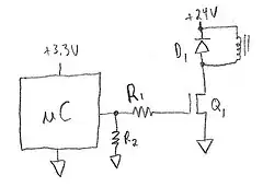
The short answer is that you need a freewheeling diode to conduct the current when the MOSFET turns off; the solenoid has inductance that stores energy in the magnetic field, and when you turn the MOSFET off the inductance will generate however much voltage is necessary to continue flow of that current. The resulting voltage pulse will cause breakdown in the MOSFET which causes the damage you are seeing.

You should also add a couple of resistors, one from microcontroller output to ground, to make sure it's off when your microcontroller is in reset, and the other from the microcontroller to the MOSFET gate, to add some resistive isolation between your power switch and your microcontroller.

enter image description here


edit: I just noticed you're using a BS170 MOSFET. Have you looked at the datasheet? This is a poor choice for a MOSFET used as a power switch from a microcontroller.

First of all, the MOSFET is specified at 10V Vgs. You're supplying it from a 5V microcontroller. You need to make sure you use MOSFETs that are "logic level" and have on-resistance specified at 4.5V or 3.3V Vgs. (I suggest you not use ultra-low voltage MOSFETs as there's a possibility of it turning on weakly when you think it is off.)

More importantly, it's a small TO-92 MOSFET specified at 5 ohms max Rdson at 10V Vgs. This MOSFET is fine for very small loads like LEDs drawing a few milliamps. But solenoids generally draw tens or hundreds of milliamps, and you need to calculate I2R loss in your MOSFET for the current load it draws, and make sure that it doesn't cause your transistor to overheat. Look at the thermal resistance R theta J-A on the datasheet and you can estimate how much temperature rise there is in the part.

Use a MOSFET in the 20V-60V range that has a lower on-resistance -- as I said in my comment, we need to know how much current your solenoid draws if we're going to help you.

Jason S
  • 13,950
  • 3
  • 41
  • 68
  • 2
    A catch diode is absolutely needed here, but that's not the cause of "fails after a few seconds" type of failure. – markrages Mar 31 '12 at 19:08
  • Thanks for your quick answer! Silly of me that I didn't specify the valve. This is the one: http://www.ebay.com/itm/290655223999 It has some data, including the current: 500 mA. So I'm using the wrong mosfet? Btw, where do you see that it's rated for 10V Vgs? On the datasheet I see "+-20" in the VGss row. – Dyte Mar 31 '12 at 22:30
  • 1
    I just changed "rated for" to "specified at". You can use up to +/-20V gate-to-source voltage w/o damage, but if you want the MOSFET to have a guaranteed drain-source resistance, you need to provide 10V gate-to-source, at which point the on-resistance is at most 5 ohms, typically 1.2 ohms, at 200mA load (see Rds(ON) on page 2). At 5V gate-source, it is going to be a higher resistance, so you're talking a watt or two of power dissipation of I2R... all you know is it's probably several times higher than 1.2 * (0.5A)^2 = 0.3W... until the device overheats and fails. – Jason S Mar 31 '12 at 23:03
  • I would add a zener diode to protect MOSFET's gate-source. Would it be an over-kill? – abdullah kahraman Apr 01 '12 at 08:07
  • @JasonS: The freewheeling diode did the trick! So my problem is solved! About your last comment, the valves will never be powered for longer than ... let's say 10 seconds (usually only a few seconds). So I guess I'm safe with this setup? Glad it works now in any case :-)) Thanks a lot for helping out. – Dyte Apr 01 '12 at 11:51
  • hmmm... well, you're lucky for now. If you need this to be running successfully for a long time, switch to a logic level MOSFET with lower on-resistance. – Jason S Apr 01 '12 at 13:43
  • 1
    @abdullah: Not overkill, rarely needed though unless there's a risk of noise causing gate/source voltage to exceed safe levels. – Jason S Apr 01 '12 at 13:44
  • @JasonS: what do you suggest as a value for the R2 resistor in your diagram? Also in the 100-1Kohm range? Thanks! – Dyte Jun 06 '12 at 11:25
  • 10K is sort of the default resistor value in logic-level circuit design -- it's large enough to keep current flow low, but low enough to keep EMI and leakage current effects from being a problem. We generally use 10K pullup or pulldown resistors in our designs, and that would be appropriate here. You could probably get away with a 100K pulldown. I wouldn't go any lower than 10K unless you needed a super-fast-turnoff time for the MOSFET in case of power supply failure. – Jason S Jun 06 '12 at 12:47
  • @Dyte - MOSFET **MUST** be fully turned on by 3V or lower logic level to work properly with 3V3 supply microcontrollers. Zener from gate to source HIGHLY recommended, especially with inductive loads. Reverse diode (or equivalent) across inductive loads is absolutely essential. – Russell McMahon Jun 08 '12 at 03:06
  • Russell: In 16 years of design I've never had to use a zener from gate to source. I suppose if the layout has a lot of parasitic inductance between MOSFET source and the microcontroller's ground, then yeah, it could mess up the gate drive waveform, and a zener would help protect the MOSFET gate, but there's a bigger problem there, as oscillations in the gate drive could cause very large switching losses. – Jason S Jun 08 '12 at 12:15