6

Here's a link to the (crummy) schematic:

enter image description here

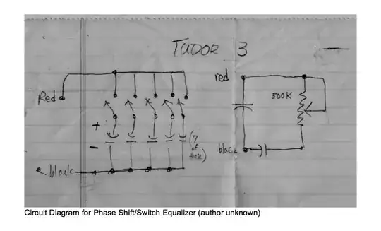
It's a filter/phase shift designed by the experimental electronic musician David Tudor, for use in destabilizing audio feedback loops.

The circuit seems unclear to me, and I don't understand the signal flow, or the use of capacitors here.

Thanks!

stevenvh
  • 145,145
  • 21
  • 455
  • 667
Greg
  • 421
  • 1
  • 5
  • 11

1 Answers1

7

Take a look at http://en.wikipedia.org/wiki/RC_circuit under the Parallel circuit section.

That circuit allows you to adjust the resistance (with a pot) and adjust the capacitance by opening or closing switches. So, you can have any combination of switches open or closed to get a different effective capacitance.

The capacitor between Black and Red is just always added with the switched capacitors.

The pot and capacitor at the end is a Snubber, find more info at http://en.wikipedia.org/wiki/Snubber

Kellenjb
  • 17,509
  • 5
  • 51
  • 87
  • 1
    Awesome, very helpful answer. – Greg Jun 08 '10 at 23:17
  • 1
    as a side note, if he does crazy stuff and causes odd ringing sounds to come out of it. Or if after there are sounds there are after effects he designed this system to use the inductance of the wiring to cause ringing to get extra noises. – Kortuk Jun 09 '10 at 04:17
  • Kortuk - that's interesting, can you be a bit more clear? It definitely sounds like that's a possibility. Is it some sort of resonance? – Greg Jun 09 '10 at 15:14