0

I was working on a project with a LM741N and I accidentally hooked up the circuit wrong, and I noticed some strange behavior. I was trying to amplify the 3.3V output of a micro-controller to 6V, but instead I got basically a switch. If the pin was high, the output of the op-amp was 0V, and if the pin was low, the output was 11.6V (the op-amp V+ was 12V). I was wondering if anyone could tell me if this behavior is normal and if so what is it called, or if it will damage the op-amp.

To me this behavior is extremely useful, if it is "normal" behavior what would be the ideal circuit?

Here is the circuit I accidentally hooked up: Circuit

Reid
  • 2,030
  • 1
  • 21
  • 38
  • 4
    A comment on the schematic: someone here could kill you :). Why don't you rotate the Op-Amp, so then the supply pins are on the right side without making that strange swastika? And why do you have to put input and output on the same side? It has them on opposite sides for a beautiful reason! – clabacchio Mar 29 '12 at 06:16
  • 2
    What a mess. In addition to what clabacchio said, flip the power pins of the opamp around so that positive is on top and negative at bottom. Didn't you notice how you had to contort the power feed to hook it up. See http://electronics.stackexchange.com/a/28255/4512 – Olin Lathrop Mar 29 '12 at 12:26
  • It was a quick schematic. It was not supposed to look pretty, just be functional. – Reid Mar 29 '12 at 16:41
  • @Reid - If you're showing it to other people, *make it readable*. Doing it quickly is no excuse. – Connor Wolf Mar 31 '12 at 00:25

1 Answers1

3

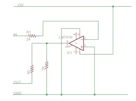
Any opamp can be used as a voltage comparator. Basically feed it two voltages, one on the + input and the other on the - input and the output will tell you which input is higher than the other. This Wikipedia page explains it fairly well, so I won't bore you with my own description.

I will say that your circuit could be doing something slightly different. Most opamps, including the LM741, don't deal well with input voltages that are close to the power rails. Even so-called "rail to rail opamps" have limits on how close an input can get. Your schematics don't show how you connected power to the opamp, so I can't be sure. However, if you connected the negative power pin to GND then this opamp could be operating outside it's normal input voltage range in which case all bets are off as to how it will behave. Even so, it is at least trying to work as a comparator.

Update: I'm adding specific examples of rail-to-rail I/O (RRIO) opamps.

TI OPA170: Advertised as having rail to rail OUTPUTS. The datasheet says that when driving a 1 mA load the "output voltage swing from rail" will be a minimum of 115 mV with no maximum specified (page 3 of the datasheet). Now I might be interpreting the datasheet incorrectly, but I read that as saying they offer no guarantee of RRO's. A couple of lines later they say that over the entire temp range the output voltage won't be better than 0.35v from the rails. This chip doesn't claim to have rail to rail inputs, which is good because the input can't get closer than 2.0v to the V+ rail.

TI LM7321: Advertised as having RRIO. Page 4 of the datasheet says that the output could, under some conditions, be 450 mV from either rail, and typically about 100 mV. Common Mode Input Voltage Range IS rail to rail over entire temp range.

On Semi LMV981: Advertised as having RRIO. Page 3 of the datasheet shows that the output isn't guaranteed to get closer than 170 mV from the rail. Also, it specifies that the Input Common-Mode Voltage Range is rail to rail for limited temperature ranges.

Bottom Line: Your mileage (kilometerage?) may vary. Read the datasheets carefully and don't rely on the bullet list of features on the first page.

  • I connected the input to a micro-controller that outputs either 0 or 3.3 volts. Will this damage the op-amp in any way, or could I use the circuit reliably? If not what could I use? – Reid Mar 29 '12 at 05:32
  • 1
    @Reid No danger to destroy the Op-Amp this way – clabacchio Mar 29 '12 at 06:18
  • Can you give an example of a rail-to-rail opamp that doesn't allow input voltages all the way to the rails? – markrages Mar 30 '12 at 02:54
  • @markrages Most op-amps don't allow rail-to-rail inputs. Unfortunately older op-amps like the LM741 don't spec it in any obvious way. In this case you can see that with the power supply at +/-15v the input voltage range is +/-13v typ, and the output range is +/-14 typ. With this datasheet it is not obvious what happens if the power rails are lower than +/-15v, but experience says that the input range will always be 2-3 volts less than the power rails for this part. –  Mar 30 '12 at 13:42
  • I was mostly curious about your statement: "so-called 'rail to rail opamps' have limits on how close an input can get." I've used RRIO amps in the past and never encountered this. μA741 is definitely not RRIO! – markrages Mar 30 '12 at 21:16
  • @markrages In the past I've looked at datasheets that advertise the parts as RRIO, but in reality have very small non-rail-to-rail-ness. Where the LM741 can't get closer than about 2v to the rail, some RRIO chips can't get closer than 0.05v or even less. While still nice, that's not RRIO in my book. Bottom line, read the datasheets carefully and if they don't say in numbers then it's not RRIO. I'll look to see if I can find an example for you... –  Mar 30 '12 at 22:32
  • @markrages I added examples of real chips and RRIO performance. –  Mar 30 '12 at 23:10
  • All your examples have rail-to-rail input CM range. The LMV981 just has slightly worse CMRR over temperature when you're at the rail. (40 dB instead of 50 dB.) – markrages Mar 31 '12 at 02:34
  • @markrages Yes, but the point is that they all suffer something when getting close to rail to rail inputs. CMRR, temperature, and (probably) THD+N. Just because there is a bullet item that says it's RRIO doesn't mean that you can use it without paying close attention. –  Mar 31 '12 at 02:49