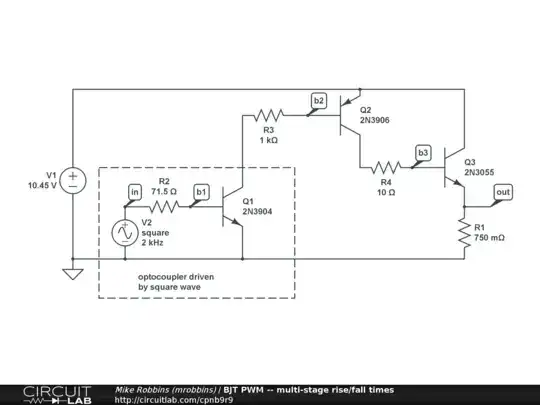
I constructed this circuit in the simulator Multisim11. It should switch current 15A trough resistor R1 for PWM regulation. I need to make it work for frequency 2kHz. The function generator XFG1 on the left top simulate output from TTL technology, which control switching power on R1. All active components are faster than 4 MHz, so it should work, but it is not working for that frequency 2kHz.
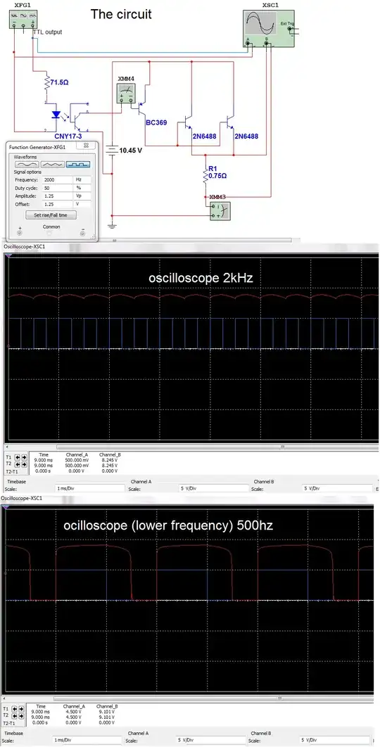
As you can see on oscilloscope there are two curves. The blue one is the signal from TTL and the red one is the voltage on resistor R1. As you can see it is switched on whole time. The blue curve have minimal effect for the red one.
I tried to set lower frequency (500Hz). Here you can see the problem. Rising edge looks good there is not any delay, but there is big delay with falling edge. It keeps switched on about 0.5ms after TTL signal fell.
So this is problem, does somebody know how to solve it in this circuit?