-1

I have a micro-controller based project. I am using nrf51822 as the MCU.

there are two 12V relays in my project and they are used to switch 230V AC.

These relays are controlled by nrf51822. Currently the output is connected to the normally close pin of relay. When I switch on the relay using MCU which works fine. But when I switch off the relay the MCU will restart.

MCU says that the reason for restart is power failure.

How can I solve this issue?

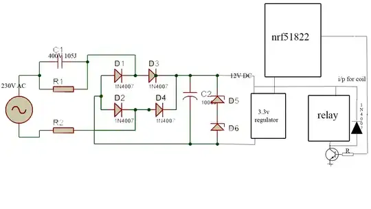
this is the schematic for the setup enter image description here

Edit: i have added a 220uf/16v capacitor between the VCC and GND of nrf51822. the problem is solved. but not with a .1uf. is this is a correct solution for this............?

iqbalpalemad
  • 61
  • 1
  • 2
  • 7
  • 2
    How do you control the relays? transistors? optocouplers? What is the power supply? Is is shared between relays and the nRF chip? Do you have enough decoupling capacitance? – filo Feb 21 '17 at 09:47
  • 1
    Do we assume (because you don't show a circuit) that you have protection diodes across the relay coil, that you have taken precautions to ensure that your relays do not pull current away from your device. The "switching off problem" indicates the lack of diodes. – JIm Dearden Feb 21 '17 at 10:34
  • @filo relays are controlled by transistors. the power is shared between relays and nrf chip. there is no any capacitance. here power supply used is described here [link](http://electronics.stackexchange.com/questions/126487/ac-to-dc-without-transformer-how-does-this-thing-work) – iqbalpalemad Feb 21 '17 at 10:37
  • @JImDearden fly back diodes are provided there – iqbalpalemad Feb 21 '17 at 10:38
  • I'm talking about the diode that should be placed across the coil of the relay. http://www.learnabout-electronics.org/ac_theory/images/Protection-Diode.gif – JIm Dearden Feb 21 '17 at 10:44
  • the diode is placed across the coil. – iqbalpalemad Feb 21 '17 at 11:23
  • 1
    It the diode across the coil fast enough? What diode are you using? Can you actually show us the relevant portions of your circuit, including all your power caps? – Scott Seidman Feb 21 '17 at 13:21
  • 1
    What type of AC loads are you switching with the relays? Are they inductive? If so, how are you suppressing inductive spikes there? – Tut Feb 21 '17 at 16:24
  • 2
    Please show schematic. – markrages Feb 21 '17 at 16:27
  • 2
    See also: [PIC16F628A Resetting after relay turned off](http://electronics.stackexchange.com/q/101815/25328) – Tut Feb 21 '17 at 16:32
  • Do you have a cap on the output of the regulator? The power pins on the nrf? – Scott Seidman Feb 22 '17 at 11:44
  • You still haven't answered my question about whether you are switching an AC inductive load with your relays. Your solution appears to be a "band-aid" fix. If you are switching an inductive load, see my answer in the link I provided above. You may keep the cap, but also fix the source of the spike. It is better for your relay contacts. – Tut Feb 23 '17 at 12:34
  • i am using a fan and a bulb as load – iqbalpalemad Feb 27 '17 at 04:41

2 Answers2

1

i have added a 220uf/16v capacitor between the VCC and GND of nrf51822. the problem is solved. but not with a .1uf. is this is a correct solution for this............?

The nRF51 (and most micros for that matter) need to have decoupling on their power supply lines. You'll often find a big cap (10uF) in parallel with a much smaller cap (10nF or even smaller) to provide a reservoir or "tank" of energy. It smooths out the often heavy and fast power draws that micros are known to produce.

This question and answer can explain it far better than I can. What is a decoupling capacitor and how do I know if I need one?

Power supplies are slow...they take roughly 10 us to respond (i.e. bandwidth up to 100 kHz). So when your big, bad, multi-MHz microcontroller switches a bunch of outputs from high to low, it will draw from the power supply, causing the voltage to start drooping until it realizes (10 us later!) that it needs to do something to correct the drooping voltage.

To compensate for slow power supplies, we use decoupling capacitors. Decoupling capacitors add fast "charge storage" near the IC. So when your micro switches the outputs, instead of drawing charge from the power supply, it will first draw from the capacitors. This will buy the power supply some time to adjust to the changing demands.

The "speed" of capacitors varies. Basically, smaller capacitors are faster; inductance tends to be the limiting factor, which is why everyone recommends putting the caps as close as possible to VCC/GND with the shortest, widest leads that are practical. So pick the largest capacitance in the smallest package, and they will provide the most charge as fast as possible.
CHendrix
  • 1,387
  • 9
  • 19
0

Firstly check the voltage of output pin in nrf51 without connecting transistor circuit if it's voltage level changing according to setting pin High & Low. If nrf51 reset then it's firmware error.

If firmware working fine then check transistor circuit. Is it properly become High & Low(if not change your transistor). Have you properly connected both GND (nrf51 & transistor).

Check you relay config & circuit (eg working voltage & current level etc)

If all good then lastly change your load.

Your problem look like similar: link