5

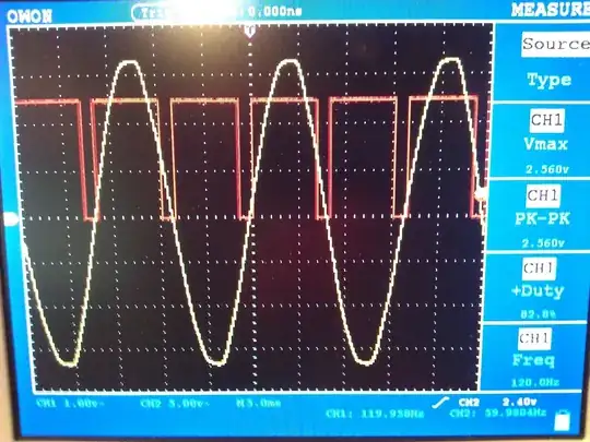
I have a dimmer circuit that produces the following wave forms.

Red: Triac Gate Signal
Yellow: 120v 60Hz AC Wave (not triac output)

I would assume that given this signal, the triac should flip on and the light and it should be at nearly 100% brighness. However, this is not what's happening. Itstead, the light doesn't turn on at all. Can anyone explain why this might be? If I change the gate to be always triggered (i.e. always voltage to the gate), the light turns on to 100% brightness as expected. Is it possible that the resistor sitting before the triac gate is too high (56 Ohms)?

AC Wave with Triac Gate Pulse

The circuit is essentially the same as this one:

enter image description here http://www.arduino.cc/cgi-bin/yabb2/YaBB.pl?num=1276992650/0

m.Alin
  • 10,638
  • 19
  • 62
  • 89
Matt Ruwe
  • 1,957
  • 7
  • 23
  • 35
  • I dont have time for a real answer, but it looks like IC1 has zero edge detection. What net are you measuring? – Kortuk Mar 26 '12 at 19:45
  • I'm pretty new to this stuff, so you'll have to bear with me. Not sure what you mean by "net", but since IC1 has zero edge detection, does that mean I need to send the pulse to the IC1 (pin 1 & 2) *before* the zero cross actually happens? – Matt Ruwe Mar 26 '12 at 20:26
  • @Kortuk After thinking about your comments a bit more, I think you're asking how I got the zero cross. I left that part of the circuit out of the question to avoid confusion as it didn't really have anything to do with it. I'm using another optocoupler to do that part and then feeding it's output into the micro controller. – Matt Ruwe Mar 27 '12 at 02:44
  • I meant the Triac signal you are quoting, are you measuring at the pin labeled 1 for the IC or the pin labeled 4? – Kortuk Mar 27 '12 at 13:15
  • @Kortuk The measurement was taken from a different part of the circuit (not shown in the schematic). I'm using another opto coupler as a zero cross detector to know when to push the signal high. – Matt Ruwe Mar 27 '12 at 16:01

3 Answers3

8

The TRIAC driver that you chose (MOC3041) has a Zero Voltage Crossing detection circuit included. That means that you can't really control when to switch the TRIAC on. The Zero Voltage Crossing detection circuit will automatically turn your TRIAC on when the AC wave reaches a zero crossing point.

If you want to do dimming, you'll have to use an triac driver without Zero Voltage Crossing detection included, often called a Random Phase triac driver, like this one: MOC3052-M.

m.Alin
  • 10,638
  • 19
  • 62
  • 89
  • Any idea why the original author of this circuit called for that IC? The original purpose was as a light dimmer, but the circuit is notably missing a zero cross detector to get the starting point from which to delay. I'm thinking I must be messing up the software. Thoughts? – Matt Ruwe Mar 26 '12 at 22:19
  • 1
    The original dimmer was probably using phase counting. e.g. dimming by removing entire cycles to the load. Think of it as a kind of pulse width modulation. If you only give the lamp 1 out of every 10 entire cycles, then you have a 10% duty cycle. You don't need to synchronize to the line if you assume 50Hz (or 60Hz) line frequency. – akohlsmith Mar 27 '12 at 11:27
  • 2
    @MattRuwe, When you turn on a triac at a zero crossing point it is much less stressful to the triac and the radiation you generate is much less. There is going to be a sudden fast switch if you turn on part way through and that means high frequency transients(if you have not been taught this yet trust me, the faster a rising edge the higher frequency the signals), this can easily cause high unintentional radiation which can cause FCC problems. – Kortuk Mar 27 '12 at 13:22
  • 1
    @Andrew - A simple test is sufficient to abandon that idea. At 50/60Hz the maximum frequency for 10% duty cycle would be 5/6 Hz and the lamp would flicker like hell! I guess the schematic was used in a switch application, not a dimmer. – stevenvh Mar 27 '12 at 14:40
  • 2
    @M.Alin I ordered/received the IC you suggested and the circuit is now working beautifully. Thank you for your help! – Matt Ruwe Mar 29 '12 at 11:50
  • @MattRuwe I'm glad to hear it :) – m.Alin Mar 29 '12 at 12:38
3

M.Alin had posted the answer to this question, but deleted it for some reason (too bad because I would've marked it as the answer). After further investigation based on his comments (and the comments from Kortuk in the question) I found that I need to use a MOC3051 instead of the MOC3041 specified in the original schematic. The difference is that the MOC3041 is a zero cross triac driver which essentially means that it will not turn the gate on until the signal is high AND the AC zero cross has occurred. This has a great simple description of how it works.

I imagine this could be useful in a number of circumstances, but for the dimmer it makes more sense to me to slice the AC signal as opposed to turning on only a select few "half cycles" (e.g. every other cycle or every 3rd cycle, etc), which I suppose is what the original designer of the circuit intended. I would imagine that there would be less of a "strobe" effect with the light through the use of slicing, but I certainly could be mistaken here.

It's funny how this stuff doesn't make a bit of sense until someone describes it and then I feel totally stupid for even asking the question. =D

Thanks guys!

Matt Ruwe
  • 1,957
  • 7
  • 23
  • 35
  • @m.Alin - I don't understand why m.Alin deleted his answer either, since it's the perfect answer. m.Alin, please undelete it so we can upvote it. – stevenvh Mar 27 '12 at 10:28
  • @Matt I'm glad to be of some help in your problem – m.Alin Mar 27 '12 at 10:39
  • Until you know what zero crossing is for you would not know to expect the functionality of it. – Kortuk Mar 27 '12 at 13:17
  • @Kortuk That's a good point. Is it possible to discover this from the datasheet? I read it several times, but didn't see anything about how it would cause the IC the behave. Maybe it's in the graphs near the bottom or it is just assumed that anyone using the circuit would understand what the zero cross was for. – Matt Ruwe Mar 27 '12 at 15:57
  • @Matt, they assumed, it is something they dont use space on all the time because you only need to learn it once. – Kortuk Jun 22 '12 at 15:45
-2

You have to reduce the period of duty cycle

  • This has already been answer and this answer is a bit short. It seems the zero crossing is the primary issue. I have to agree with the above answers. If you can prove me wrong edit it in and let me know. I hope you continue to take part in our site after this. – Kortuk Jun 22 '12 at 15:50