3

I have 3 RGB LEDs with common anode, a shift register and a microcontroller. Currently I have connected a series resistor for each cathode of the RGB LED, so there are 9 resistors in sum. I wondered If I could use only one resistor per RGB LED because there is always only one active RGB LED.

Take a look at this picture and tell me if this is possible and why not if it isn't:

enter image description here 
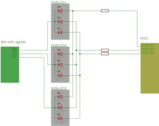
http://www.abload.de/img/schm2yw8.png
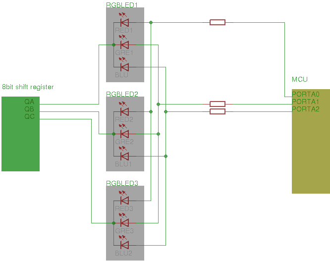
Thank you.

Connor Wolf
  • 31,938
  • 6
  • 77
  • 137
arminb
  • 1,622
  • 4
  • 21
  • 34
  • Related (or even kind of the same question): http://electronics.stackexchange.com/questions/13613/6-leds-in-parallel-with-a-single-resistor-to-simplify-soldering – PetPaulsen Mar 25 '12 at 15:02

3 Answers3

4

If you can make sure there's only one LED on at any time three resistors will do, like you've drawn.

stevenvh
  • 145,145
  • 21
  • 455
  • 667
  • yes but note that i'm switching very fast between the leds (multiplex) so that the human eye only see 3 lightning LEDs. isn't this taking any effect? – arminb Mar 25 '12 at 15:09
4

LEDs and the 74HC595 can go quick enough, no problem. But, note a few things:

  • You're multiplexing LEDs, that means that if a LED is constantly on it only gets 1/3 it's normal current. This is because it's only on for 1/3 of the time (2/3 for other LEDs).

  • Well, if you want full brightness per LED.. increase the current. You could, but then get the problem that you can burn out LEDs (if software gets stuck, during programming or flashing) and the hardware needs to support it. The 74HC595 can only sink 25mA per pin. The microcontrller probably a similar amount as well. This could already become an issue if you turn on Red Green and Blue at once all at 20mA. You may need to add a few MOSFETs or transistors that the shift register will drive, instead of straight on the shift register. Of course you don't always need to drive them that high, 5mA each LED is sufficient in most cases.

The only time I had trouble multiplexing a bunch of LED's was when I picked the wrong multiplexer. I had 13 7-segment displays setup. The segments would be driven via a 74hc595, buffered with some MOSFETs to switch the positive rail of the supply. The display was selected via 13 N-MOSFETs switching the GND of each display. I picked a 16-channel multiplexer for this, but forgot to look what it was. Turns out it was analog multiplexer.. Because I used N-MOSFETs they had to be 'forced' on/off. A analog multiplexer doesn't pull or push the output, it either connects it to the input or keeps to pin floating. With a floating pin the N-MOSFET wasn't turning off quick enough (tiny 'capacitor' inside the gate kept it on for 3 seconds).

I had to put a pull-down resistor on each gate to turn off faster, but had to limit the value to something the analog multiplexer could drive sufficiently. I was multiplexing at about 1kHz (which is quite slow for 13 segments) , but in the end had I programmed intermediate cycles to turn of the displays first, give it some turn-on time, re-set new display settings and turn it on. I can only actively use the display for like 70% duty cycle, 30% is wasted to turn on/off of the gates. It limited the amount of light from the displays, fortunately I only use the displays in a dark environment.

In your case you may see similar things if you leave the LEDs on while reprogramming the shift register, for example. This effect may be very small, because it's happening very fast.

Hans
  • 7,238
  • 1
  • 25
  • 37
  • Thanks for that answer. To sum it up: it's possible but dangerous while the programming process. To be on the safe side disconnect all LEDs / the 8bit register. – arminb Mar 26 '12 at 12:45
  • 1
    "Safe" would be connecting the shift register bits to FETs, so driving a 1 on the shift register is required to turn the LED on. Then connect the shift register's reset pin to the system reset, or some circuit that ensures the shift register is reset when not in use. This will ensure your LEDs are off at these times. – Mike DeSimone Mar 26 '12 at 13:47
1

Not sure why you're using the shift register instead of three MCU pins. In any case, this is called multiplexing, or scanned, LEDs, and is a very common configuration (since the number of resistors and pins varies O(log N) with the number of LEDs, instead of O(N)).

Human vision has trouble seeing anything faster than about 10 ms, and can put up with a lot slower. Note that TVs are often scanning the screen at 50 or 60 Hz. So if you scan a lot faster than that, nobody will notice.

In your shift register case, you set up an interrupt to go off every so often, say 1000 Hz (1 ms intervals). This gives you about 330 scans per second (frequency divided by number of LEDs; you want to keep this number over 100 Hz or so). Each interrupt, the pins are updated and the shift register shifted. The code would probably look like this:

int ledNum = 0;
int colorLED[3] = {0}; // Sets all elements to 0.
// Colors: black = 0, red = 1, green = 2, yellow = 3, 
// blue = 4, magenta = 5, cyan = 6, white = 7

Interrupt()
{
    // Load a 1 into the SR if this is the start of the cycle.
    if(ledNum == 0)
        SR_D = 1;
    else
        SR_D = 0;

    // Set the color.
    PORTA = (PORTA & ~7) | (colorLED[ledNum] & 7);

    // Clock the shift register.
    SR_CLK = 1;
    SR_CLK = 0;

    // Update for next loop.
    ledNum = ledNum + 1;
    if(ledNum == 3)
        ledNum = 0;
}

Note this only gives you 8 colors. For more, you'll need to increase your scanning rate because you'll be switching the LEDs with PWM. Example code for 4 bits per color, which gives 4096 colors and needs 15X the interrupt rate (15 kHz, or 0.067 ms):

int ledNum = 0;
int pwmStep = 0;
int colorLED[3] = {0}; // Sets all elements to 0.

Interrupt()
{
    // Load a 1 into the SR if this is the start of the cycle.
    if(step == 0)
    {
        if(ledNum == 0)
            SR_D = 1;
        else
            SR_D = 0;

        // Clock the shift register.
        SR_CLK = 1;
        SR_CLK = 0;
    }

    // Set the color.
    int reg = PORTA & ~7;
    if((colorLED[ledNum] & 0xF) > step)
        reg |= 1;
    if(((colorLED[ledNum] >> 4) & 0xF) > step)
        reg |= 2;
    if(((colorLED[ledNum] >> 8) & 0xF) > step)
        reg |= 4;
    PORTA = colorLED[ledNum];

    // Update for next loop.
    if(step == 0)
    {
        ledNum = ledNum + 1;
        if(ledNum == 3)
            ledNum = 0;
    }

    // Next PWM step
    step = step + 1;
    if(step == 15)
        step = 0;
}

Note that the number of steps in PWM is the same as the maximum value, not one higher. So four bits, which can represent 0-15, needs 15 steps, not 16.

Optimizations are, of course, left as an exercise for the reader.

One final thing to check is that the shift register pin is actually capable of sinking the current from three LEDs at once, given your resistor values. If not, you'll need to get some FETs or BJTs to switch the LEDs' common-cathode pins.

Mike DeSimone
  • 4,705
  • 17
  • 22
  • Thank you. I'm using shift register for practicing. Maybe I'll adapt more LEDs in future to get a RGB-LED matrix. In this case I'd need more than three output pins from the MCU. – arminb Mar 26 '12 at 12:49