2

I'm designing a PCB using this component http://www.ti.com/lit/ds/symlink/afe4403.pdf

And from the datasheet page 90 layout guidelines I found point(2) which says

If the INP, INN lines are required to be routed over a long trace, TI recommends that VCM be used as a shield for the INP, INN lines.

And I got a reference circuit in which they had this

enter image description here

So normally when guard trace is required I put a GND trace with VIAs and double spacing on either side.

My question is, having bypass cap is always a good practice or only useful if the circuit demands?. How to determine a long trace,any rules or standards?. How to route such trace in PCB, do I've to put the cap close to source or destination end?.

Thanks

Dee
  • 369
  • 4
  • 19

1 Answers1

1

Without knowing what the frequency content of the Vcm line or knowing what is driving the Vcm line, the reasons are speculatory as to why you would need the 10nF cap on the Vcm line.

Voltage references need bypass capacitors for stability and to limit the bandwidth of the feedback loop. When you extend the trace across the board you are adding inductance, which is going to change the load of the reference, to stabilize this you add a cap. Which is probably the function of that cap.

Since it is not known what the designers intended we can only infer as to why. If the datasheet suggests it its a good idea to follow the engineers suggestions because they design, build and test the devices.

To answer the other question: the length of a trace will add parasitics. You can use a PCB trace calculator to find the inductance, resistance, capacitance and transmission line effects. Normally these effects are in the range of nH's, 100's of micro ohms and pF's so they will matter only to higher frequencies (+50Mhz - kind of a nebulous number). But if your amplifier has bandwidth in this range then you need to worry about it.

schematic

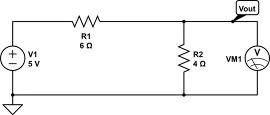
simulate this circuit – Schematic created using CircuitLab

Run the guard trace all the way around the wires to the sensor. If you using a cable with a shield (and you should) then tie Vcm to the shield. The principle here is that Vcm provides the same voltage potential as the inputs and minimizes leakage and EMI.

Voltage Spike
  • 75,799
  • 36
  • 80
  • 208
  • Thanks for the answer. I'll check with frequency content and find out the necessity. Coming to how you would do the PCB routing with resistor and cap, could you please explain little more. Consider the image in the link https://bertsimonovich.files.wordpress.com/2013/04/clip_image002.gif and let me know at which point you would connect resistor and capacitor. AFAIK the res and cap should be close to source pin (VCM). – Dee Feb 16 '17 at 19:35
  • Actually scratch that last thought on the resistor, I've included a diagram – Voltage Spike Feb 16 '17 at 19:45
  • Great! Thanks and this makes sense. But one last doubt, in your diagram you've used the guard trace covering both the INN and INP separately with a junction. Actually that can be done if there is enough space to route but in case there isn't then is it good to go with single guard trace in between like in the image I shared?. – Dee Feb 16 '17 at 19:53
  • Yes, you can put INN and INP together or just one trace between or put them in a plane of Vcm – Voltage Spike Feb 16 '17 at 20:04
  • Thanks. I've just tried in Altium to see how it works. Check this pic link and let me know if its acceptable. https://yadi.sk/i/mZr1lW3Z3EBG35 – Dee Feb 16 '17 at 21:05
  • I'll only use links on imgur – Voltage Spike Feb 16 '17 at 21:05
  • Sorry, give me few mins I'll upload it to imgur – Dee Feb 16 '17 at 21:07
  • I'm really sorry I'm unable to make an account on imgur. All I get when I click register button is this message: {"data":{"error":"Imgur is temporarily over capacity. Please try again later."},"success":false,"status":500}. I've uploaded in dropbox if you don't mind checking. Thanks. https://www.dropbox.com/s/johren7qnv3ogn0/Screen%20Shot%202017-02-17%20at%2002.22.46.png?dl=0 – Dee Feb 16 '17 at 21:21
  • You don't have to, just click on the image button and add it that way, if you don't want it in the post then delete the link the image will remain – Voltage Spike Feb 16 '17 at 21:36
  • Ok done. http://imgur.com/a/Mqfvn – Dee Feb 16 '17 at 21:50
  • Sorry previous link not working..Check this http://imgur.com/a/2Guh2 – Dee Feb 16 '17 at 23:23
  • What you have looks fine to me. – Voltage Spike Feb 16 '17 at 23:33
  • I'm not responsible for your design though, the principle is to guard the same potentials. The INN line is not at the same potential and its a 'short' run. I'm not sure what the leakage requirements are, but in most cases it doesn't hurt to guard a signal with an unchanging potential. The INP line looks good. – Voltage Spike Feb 16 '17 at 23:36
  • No worries at all and thanks for answering my doubts. I completely agree that you or any other from here will not be responsible for my design. Yes, I'm still looking to fix the shorter trace a I've a tight components with BGA 0.5mm pitch. Actually I can't move the decoupling caps which is why I had to route with irregular traces. But anyway thanks again. I'll mark this as answer. – Dee Feb 16 '17 at 23:46
  • Glad I could help – Voltage Spike Feb 16 '17 at 23:47
  • Sorry one last thing I wanna show you http://imgur.com/a/uyHHp I've done some changes and think this looks better. I used 7mil for the INN and INP and 3.2mil for sheild traces...Your comments please? – Dee Feb 17 '17 at 00:17
  • That is more appropriate for shielding the signals because the datasheet requests that both signals be shielded. You also may want to run the shield out on the other side of the board where the sensor is too – Voltage Spike Feb 17 '17 at 00:20
  • You might be right and think to be on safe side its better to do. I can try pull a VCM Sheild trace from the same VIA on to the bottom side where sensor is present. – Dee Feb 17 '17 at 00:27
  • Done. http://imgur.com/a/61Mid Thanks for the comments. – Dee Feb 17 '17 at 00:39