1

I need to design a system which will allow me to transmit data via ultrasound. I'm using BPSK modulation, the transducer frequency is 40Hz and the chipping frequency is 5kHz (however I can easily change that). The BPSK is done using a microcontroller and is connected to the transmitting transducer (after amplifying the voltage to about 15V). My problem is that the receiver doesn't detect the phase shift, it simply outputs a 40kHz sine wave. Any thoughts?

Top: Modulated BPSK signal, bottom: binary data that i want to send

EDIT: I have now added a photograph of the scope on the receiver. However the actual phase shift of the receiving signal is not show. It does eventually shift but it takes a few cycles.

PSK receiver

1 Answers1

2

Most 40,000 Hz piezo transducers are high-Q, which means that once you get them oscillating, changing amplitude or phase takes awhile. Or it requires an extremely large transient. My measurements of a cheap piezo transducer revealed an equivalent circuit like this:

schematic

simulate this circuit – Schematic created using CircuitLab The components L1, C1, and R1 are electrical equivalents of the piezo's motional parameters, and affect the amplitude of the transmitted wave. L1 and C1 resonate at a frequency slightly below 40000 Hz. C2 is an actual capacitance between the piezo plates.
If you reduce the BPSK modulation data rate to something much slower, you should see the phase change in your receiver, because both transmitting and receiving transducers have a chance to change phase before the next baud period. Be aware that a piezo receiver circuit likely has similar high-Q characteristics.
One solution here is to de-Q both transmitter and receiver piezo transducers, so that their increased bandwidth can accept a higher data rate. But you may find that sensitivity is compromised. Another solution may be to apply a very large transient at the beginning of each phase-change, to overcome the piezo's built-up motion. This won't work at the receiving end.
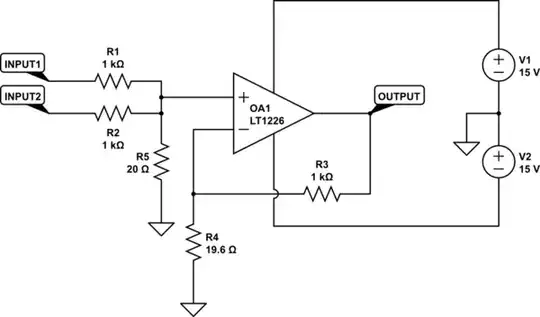
An attempt at improving transient response with this model of piezo used this circuit with some limited success:

schematic

simulate this circuit

glen_geek
  • 23,591
  • 1
  • 22
  • 50
  • Thanks for your reply! I managed to see phase shift slowly. How did you get the values for L1 and L2, are you trying to match the input impedance to that of the transducer? Do you know of any other way to reduce the oscillations? – smokingRooster Feb 15 '17 at 18:26
  • @smokingRooster L1 combines with the piezo parallel capacitance C2 to resonate near 40 kHz. R1 provides critical damping. The goal is to lower overall circuit Q, improving transient response. L1 and L2 would have to be adapted to a particular transducer, with this double-tuning approach. The Q of the double-hump response can be made lower than Q of transducer alone. – glen_geek Feb 15 '17 at 19:05
  • Thanks again, would this approach decrease the sensitivity of my transducer? Could you also point me in the right direction so I can read a bit more about this. – smokingRooster Feb 15 '17 at 21:35
  • @smokingRooster Since these piezo models are so similar to crystals, you might get some joy by searching for material on variable-frequency-crystal circuits (VXO). I think de-Q-ing resonators likely degrades sensitivity of a receiver. – glen_geek Feb 15 '17 at 22:12