5

I was studying some LED matrix designs on the Net and came across the one below:

Its design puzzled me because I couldn't tell how it limits the current through each LED and through the shift registers outputs without any current limiting resistors.

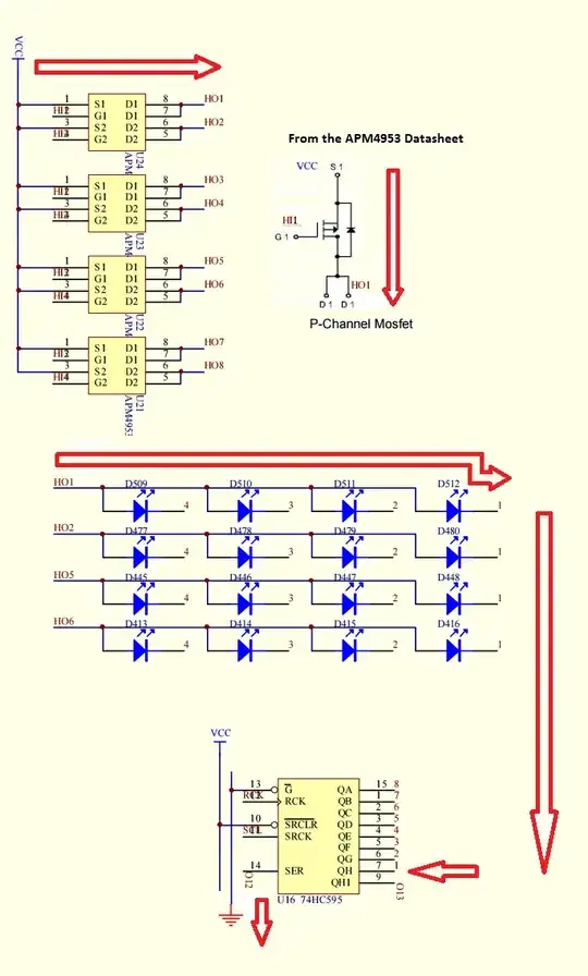
For clarity, here are the relevant parts of the schematics diagram linked above.

VCC is 5V.

Selected parts of the schematics

Here are the relevant datasheets:

As far as I can tell, to light a LED, say D512, one has to:

  • turn on the high-side PFET by setting HI1 to LOW, thus turning row HO1 on, and
  • set the '595 shift register output QH (pin 7) to LOW

In this case, the current path would be the following:

Current path

My question is: what is limiting the current through the LED and '595 QH output?

My best guess is that, somehow, the '595 is clamping the current to the desired value of 20mA, which incidentally may be the forward current intended to be pushed through a common LED indicator. Is that it? If so, why does that happen?

Another guess is that there is a specific combination of VCC, multiplexing scheme, LED forward voltage and current that magically limits the current.

In any case, is this the Right Way of Designing It(TM)? Or is this just a trick in which the '595 is being used outside its specs?
Ricardo
  • 6,134
  • 19
  • 52
  • 85
  • 1
    Note that, because the LEDs are strobed rather than continuous, it's possible to exceed their forward current rating for short times without damage. – pjc50 Feb 14 '17 at 11:11
  • @pjc50 - I realize that, but thanks for pointing it out anyway. The common LED indicators I'm used to can take up to 100mA of pulsed current, but usually at lower duty cycle (10%) than the one used in this design (25%). So that's ok for the LED. But what about the shift register outputs? Can they take it? – Ricardo Feb 14 '17 at 12:06

2 Answers2

4

I checked a few datasheets:

And I nowhere saw a current limit specified. The only thing that is specified is that you must not exceed 35mA output current (absolute maximum rating). But it doesn't say the chip itself limits the current to this value.

Now, I found another spec from TI:

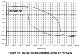
It gives (among other interesting things) the output characteristic of two 74HC chips (74HC00, and 74HC240 whose specs are closer to those of the 74HC595), and we can indeed see that you can easily get more current than the specified 35mA max. Likely, the current will be limited to about 80mA (but it certainly isn't very accurate and may depend a lot on temperature and chance):

enter image description here

Anyway, it will be much more than the 20mA you'd like to see in your circuit. There is nothing, apart from the 595 internal resistance, really limiting the current in this circuit.

So, the 595 and the LEDs are driven above their specs. For the LED, it is certainly less of a problem since there is multiplexing. So you can tolerate higher than 20mA if the duty cycle is low enough (but this often isn't clearly specified for basic LEDs).

But for the 595, if you're driving a fully lit panel, it can become a problem and may damage the chip in the long run.

This design is bad, m'kaaayy.

dim
  • 15,845
  • 3
  • 39
  • 84
  • 1
    Thanks for taking the time to answer my question properly, thus correcting the other misleading answer (that has now been deleted): +125 (upvote, accepted & bounty). – Ricardo Feb 14 '17 at 22:10
  • I guess I'll have to wait 24 hours to award the bounty to you. But consider it yours. – Ricardo Feb 14 '17 at 22:13
0

I couldn't tell how it limits the current through each LED and through the shift registers outputs without any current limiting resistors.

Through the internal resistance of the HC595s. Not uncommon - I do it all the time, on MCUs and logic devices. Certainly not advisable but done many times a day.

Ricardo
  • 6,134
  • 19
  • 52
  • 85
dannyf
  • 4,272
  • 1
  • 7
  • 9