When analyzing circuits with transistors in them, when does it make a difference whether they are MOSFETs or BJTs?
Asked
Active
Viewed 3.9k times
16
-
2The answer I wrote for this other question applies to this question: http://electronics.stackexchange.com/questions/14440/explain-what-is-a-transistor-in-plain-english/14452#14452 – Mar 21 '12 at 00:02
-
4Main differences / Rough: MOSFETS are voltage driven and are effectively controlling the resistance of a bidirectional resistive channel. Zero current (so 0 power) needed to hold on BUT substantial charge needs to be swept in and out of gate to vary drive so high current transients at gate. | BJTs are current driven and control a unidirectional junction whose ability to pass current is controlled. Bases require current related to collector current so have static power need when on. In SOME circumstances use of external drive and feedback circuitry will allow MOSFET & BJT to be interchanged. – Russell McMahon Mar 21 '12 at 01:11
-
possible duplicate of [When to use what transistor](http://electronics.stackexchange.com/questions/19233/when-to-use-what-transistor) – Olin Lathrop Mar 21 '12 at 13:06
3 Answers
13
From the design standpoint, the main and most evident difference is the base current: as Russel said, the bipolar is current-driven, which means that the current flowing into the Collector will be proportional to the current flowing in the Base (and the Emitter will output the sum for the KCL); the MOSFET instead, has a very high Gate impedance, and just putting a voltage higher than the treshold will activate it.
The bipolar transistor has a fairly constant current gain, \$ h_{FE} \$, which gives a linear response while the MOS has a quite complex response (quadratic with Vgs in saturation, depending on Vgs and Vds in "linear").
At the other hand, its fixed gain may be insufficient to use it as a switch, where a low-power input is used to turn on a high-current load: in that case the Darlington configuration (two cascaded BJTs) can help, but MOS doesn't have this problem because its current gain is virtually infinite (no Gate current as we said).
Another aspect that may be relevant is that the MOS, being controlled by charge in the Gate, doesn't like it to be floating (not connected): in that case, it's exposed to noise, and will result in an unpredictable behavior (possibly destructive). The BJT, requiring a base current, is more robust in this sense.
Usually BJTs also have a lower threshold (around 0.7 V vs 1+ V for the MOS) but this is very dependent on the device and does not always apply.
clabacchio
- 13,481
- 4
- 40
- 80
-
I have seen MOSFETs literally **eating** huge amounts of current at the gate (you neglect the gate capacitances and the transistor performance for higher operation frequencies)!! It is not a valid answer if you don't mention the model behind the transistor... otherwise, your explanation will sound like a bunch of rules that come from who knows where that transistors follow... Listing all rules a transistor follows will lead to many if's and even more contradictions. Please refer the model, it speaks by itself :) – gmagno Mar 21 '12 at 12:51
-
2@gmagno we could talk all day about models, second order and high frequency effects, temperature dependence and short channel effects; I just tried to give the OP some hints on what to expect when looking at a circuit with transistors. And there are some things that the model doesn't say, and that are more likely to be found in the datasheets. I'm just learning how many of the things that I was assuming from my theoretic knowledge were wrong. – clabacchio Mar 21 '12 at 13:40
-
I think it's fair and useful to describe how an ideal MOSFET differs from an ideal BJT, and since the ideal MOSFET has no gate capacitance it draws no gate current. On the other hand, it would also be helpful to mention the qualitative ways in which MOSFETs and BJTs differ from their ideal models. Gate capacitance should be a part of that, as should heat response. BJT's conduct better when they get hot, while MOSFETs conduct worse, thus affecting which circumstances led to thermal stability and which cause thermal runaway. – supercat Mar 21 '12 at 15:53
-
@supercat ok, I agree with both of you, and I also think that they are better understood knowing the way they work; what I say is that often it will be almost useless to know the Ids equation of MOS transistor because it contains parameters that the datasheet doesn't have. So using it will result in getting stuck. – clabacchio Mar 21 '12 at 16:08
-
@clabacchio: I tend to think of MOSFETs as having a certain gate voltage below which they're "off", another voltage above which they're "on" and will conduct a certain minimum amount of current (perhaps more, if available), and a range of voltages between in which they may do whatever they want. Not a terribly detailed model, but one which is matches reality pretty well in the defined portions, and which defines enough for many purposes. – supercat Mar 21 '12 at 17:33
-
@supercat right. What I say is that the behavior of the component defines the model, not the inverse. I mean, the model is only a way in which you describe the component, and you pick the one that you know more appropriate to the context – clabacchio Mar 27 '12 at 13:58
-
@clabacchio: A beautiful model which precisely defines a component's behavior in a way which substantially differs from the way any actual components behave is at best useless, unless component manufacturers determine that they can, at reasonable expense, produce a part which would match the model, and that the beauty of the model would make such a part useful. My point was that in many cases, rather than worrying about parameters that aren't available to precisely define a part's behavior, it's helpful to figure out what behavioral aspects you actually need to know, and ignore the rest. – supercat Mar 27 '12 at 15:14
-
@supercat I didn't explain myself properly; what I mean that you have a component and a context in which the component is used: than you pick for it the most appropriated model. For ex, you don't need Shockley equation for the LED voltage drop, usually, and you take it as a fixed value. In other cases, may be required to consider the exponential curve and maybe also high-frequency effects. And I think that this is the same you were saying before. – clabacchio Mar 27 '12 at 15:22
0
Quantitative Difference:
It really depends on the type of circuit and voltage levels you are dealing with. But generally speaking, a transistor (BJT or FET) is a "complex" component (by complex I mean, it is not a resistor, a capacitor, an inductor nor an ideal voltage/current supply), which means from a circuit analysis point of view, that you should first pick the right model for the transistor, i.e, a circuit made of non-"complex" components that represent the behavior of the transistor (google for Hybrid-pi model), in order to analyze it. Now if you look at both, BJT and MOSFET models you will be able to quantitatively compare them and understand the differences. The way you pick the right model depends on different factors, namely:
accuracy
complexity
if it is for small or large signal
(just to name a few)
Qualitative Difference:
Check some of the posts about transistors here in the forum, (for instance David Kessner's)
gmagno
- 229
- 3
- 6
-
Sorry but this doesn't answer the question, is just an abstract and somehow philosophical way to address the problem. Just talking about base current would be better. – clabacchio Mar 21 '12 at 08:26
-
Talking about base current would be underestimating the question. Usually I try to help with concepts instead of constraining my answer to obvious and what is typically heard in the classes. – gmagno Mar 21 '12 at 12:36
0
In analysing circuit this will make difference because the electrical equivalent model of BJT is different than FET because as they talk before the characteristic of BJT is not like FET .
As tou can see from this picture
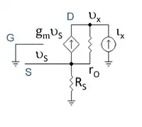
And this is due to the huge input resistor of FET .
By the way if we use a non favourable configuration the input resistor my become small as what happen when we use common gate or common base.
Yahya Tawil
- 442
- 2
- 11
- 20