3

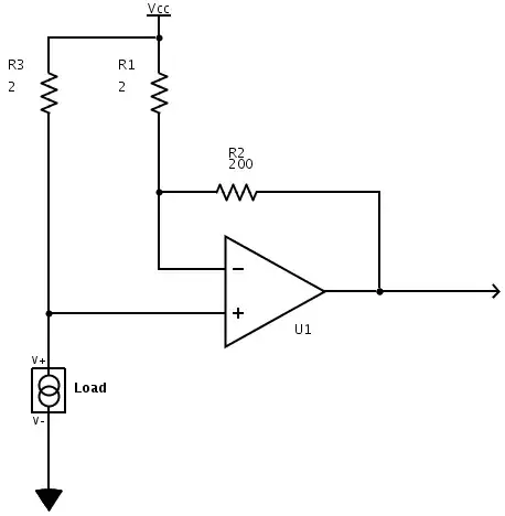
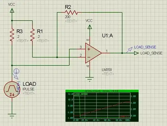
Referencing a design that uses a more expensive OpAmp, I have put together (in simulation) this current sensing circuit that uses one half of an LM358. I would like to use the other half of the LM358 to invert the output of this circuit. That is, where right now the output is 0V when there is no current through the load increasing linearly to 5V when the maximum current is reached, I would like an output of 5V when there is no current decreasing to 0V when the threshold maximum current is reached.

I have made several attempts at adding an OpAmp inverter circuit (again referencing the basic diagrams found via Google), but I have not been able to hack the two circuits together properly. How can I wire the other side of the LM358 to accomplish this?

LM358 current sense circuit

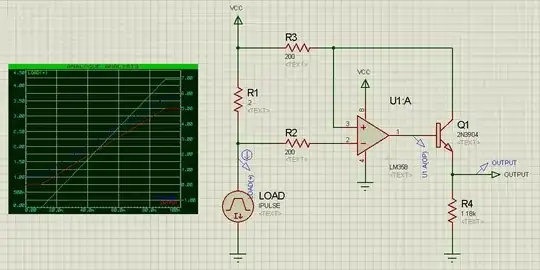
Edit: After some more playing around with the simulator I realized that I was misunderstanding the inverting OpAmp concept, among other things. I am still curious to know if there's a relatively simple analog circuit that will accomplish my stated goal, but I (think I) understand now that it's not going to be a matter of just wiring up the second OpAmp with a few resistors.

Kaelin Colclasure
  • 2,669
  • 7
  • 27
  • 37
  • I think you can swap the connections at pin 2 and 3 and then connect Q1 to Vcc instead of R3, with an another 200 ohm resistor. That way you can use other half of the LM358 for other applications. – abdullah kahraman Mar 19 '12 at 18:06
  • @abdullahkahraman: In the simulation, that gives 10V output when there's no current flowing and drops instantly to 0V when there's even the smallest current. – Kaelin Colclasure Mar 19 '12 at 18:16
  • Ah, right, because there is some kind of feedback here and the above try doesn't provide that. – abdullah kahraman Mar 20 '12 at 07:41

1 Answers1

2

Try this topology:

Inverted current sense amp

One thing to watch out for, and I don't have time to check on the LM358, is what you're asking for needs the op-amp to be a rail-to-rail type for both the inputs and outputs.

Edit: Here is the suggested circuit simulated:

Simulation

As you can see, the output ramps down from its high as soon as there is any current flowing. Substituting an ideal op-amp for the LM358 changes the voltages somewhat but not the behavior / curve.

Or have I done something incorrectly?

Kaelin Colclasure
  • 2,669
  • 7
  • 27
  • 37
The Photon
  • 126,425
  • 3
  • 159
  • 304
  • LM358 input cannot come closer than ~~ 1.5 V to V+ from memory. – Russell McMahon Mar 19 '12 at 23:22
  • Thanks, Russell. That more or less means whether OP sticks with his current circuit and bodges on an extra inverting stage, or goes with something simpler that inverts right from the start, (s)he'll need a different op-amp. – The Photon Mar 20 '12 at 00:41
  • I edited this question yesterday to attach simulation results for this proposed circuit, but apparently the edited version needs "peer review" before it becomes visible to anyone else. The summary is, the output of this circuit ramps down from its high as soon as there is any current flowing. Substituting an ideal op-amp for the LM358 changes the voltages somewhat but not the behavior / curve. – Kaelin Colclasure Mar 20 '12 at 13:31
  • It looks like I mis-calculated the amount of gain in your original circuit. Try changing R1 to 100 and R2 to 2.46k in my circuit and the new gain should match what was in your original circuit. You will have to tweak the R values to get standard values that give roughly the same gain. – The Photon Mar 20 '12 at 16:15
  • Your new simulation shows R1 and R3 as 0.2 Ohms, where previously you had a 2 Ohm sense resistor (as far as I could tell from your image). You can increase R1 or decrease R2 to reduce the gain. Increasing R1 will reduce the power consumption but might reduce accuracy by mismatching the impedance seen by the inputs to the op-amp. – The Photon Mar 21 '12 at 16:40
  • Okay, by tweaking the resistances as suggested I was able to get something relatively close... The resulting LOAD_SENSE curve looks like it tries to move rail-to-rail, but of course it can only get within about 1V with the LM358. The other problem is that it either lags following the current rise or it bottoms out before the peak current is reached (or both), again depending on the exact resistance values I try. This is all probably fix-able with a rail-to-rail OpAmp, as suggested. But I still wonder if there is a way with the LM358 (as I have those handy)? – Kaelin Colclasure Mar 21 '12 at 19:31
  • LM358 has input common mode range down to 0 V, so you could switch to low-side sensing. Or you could power the op-amp from 1.5 V higher than you're powering the load from (either by increasing the op-amps power supply voltage or dropping the voltage where you show the VCC supply port near R3 in your schematic). – The Photon Mar 21 '12 at 20:40