4

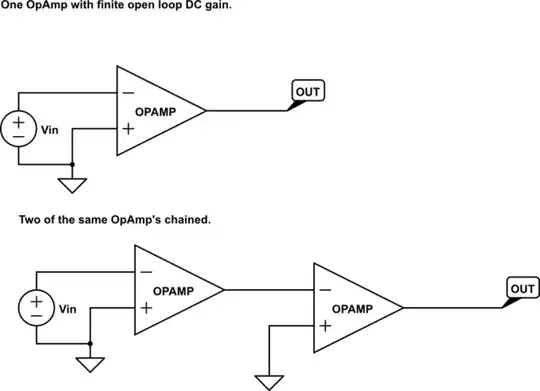
I have an op amp, it has an op amp \$A_{DC gain} \$ DC open loop gain, its ideal

The open loop gain is \$ V_{out} = A_{DC gain} V_{in} \$ (Actually \$ -V_{in} \$ in the diagram, but you get the drift)

If I chain these two op amps together, I would get \$ Vout = A_{DC gain1}* A_{DC gain2}V_{in} \$ giving me more DC open loop gain.

schematic

simulate this circuit – Schematic created using CircuitLab

Now for the question: If I do this for two ideal Opamps with DC open loop gain in a closed loop situation I should get more DC open loop gain and be able to move to higher gains.

In the top example the closed loop gain is equal to:

\$ Gain = \frac{A_{DC gain}*\frac{R_1}{R_1+R_2}}{1+A_{DC gain}*\frac{R_1}{R_1+R_2}}\$

in the bottom chaining two opamps together should improve my open loop gain

\$ Vout = A_{DC gain1}* A_{DC gain2}V_{in} \$

so I would get this: \$ Gain = \frac{A_{DC gain1}* A_{DC gain2}*\frac{R_1}{R_1+R_2}}{1+A_{DC gain1}* A_{DC gain2}*\frac{R_1}{R_1+R_2}}\$

(I also realize that flipping the other opamp negates the gain depending on if the positive terminal is grounded or the negative terminal is grounded.)

Would this work in the real world with real opamps that are not ideal? What would be preventing me from doing this?

schematic

simulate this circuit

Voltage Spike
  • 75,799
  • 36
  • 80
  • 208

2 Answers2

5

Yes - you can combine two opamps with the aim to improve the overall peformance (not only for enlarging the open-loop gain). HOWEVER, as outlined by Andy_aka you must NOT simply combine two "naked" opamps.

Instead, the second one must be equipped with an internal negative feedback (reducing gain). In each case, one of the opamp must be inverting and the other one non-inverting (stability against self-excitement).

Such a combination is called "composite amplifier" (googling for this key word gives you several alternatives). For example, such a combination can be used to combine excellent input specifications of one opamp (noise, offset, input impedance) with good output specifications (output impedance, slew rate) of another opamp. At the same time, the closed-loop bandwidth will be considerably enlarged. Hence, dc as well as ac characteristics can be inproved simultaneously.

Here is an example, where the excellent slew rate properties of a current-feedback amplifier are combined with the good input specs of a voltage-opamp.

schematic

simulate this circuit – Schematic created using CircuitLab

LvW
  • 24,857
  • 2
  • 23
  • 52
  • if I am not wrong, the reducing amplifier here is the OA1 TL081 and it is the current feedback amplifier?? – Yaakov Nov 26 '19 at 12:30
  • 1
    The last stage called CFA is a current feedback amlfier...it has very good slewing characteristics abd is combined with a voltage opamp (having good input characteristics). – LvW Nov 26 '19 at 18:37
  • thanks, despite having many Ressources to learn Op Amp and Analog circuit. I still newbie and need to take it to the next level. I see many things I don't know. do you have a tip which book i must really fully to be able to design circuit and solve them on my own – Yaakov Nov 29 '19 at 08:04
  • Yaakov.....my recommendation: Try Sergio Franco: "Design with operational amplifiers and analog intergated circuits"....(an older version is available in the internet) – LvW Nov 29 '19 at 08:36
  • Thank you very much – Yaakov Nov 29 '19 at 13:56
4

Would this work in the real world with real opamps that are not ideal?

No, unless they were really crappy op-amps.

What would be preventing me from doing this?

It's called phase margin and basically this means that if you string two op-amps together it turns into an oscillator. Here's a picture that should help: -

enter image description here

This shows the open loop response of an op-amp versus frequency for an TL084 op-amp. Pretty average sort of picture for most op-amps with low to medium speed. Note that in red I have shown the phase margin and it's approximately 50 degrees. This means that at 0 dB gain the opamp is about 50 degrees away from becoming an oscillator. If you added another gain stage to that op-amp you are basically lifting the 0 dB point and the new 0 dB point will be at a significantly higher frequency and make the phase margin either very close to zero degrees orpossibly it might go negative - that's the point where you get an oscillator.

But it's worse than this for two cascaded op-amps because the phase margin for both op-amps cascaded has to be taken into account.

So, for instance, at 200 kHz, the PM of one op-amp has dropped from 180 deg (at DC) to about 90 degrees. Cascade two identical op-amps and the combined phase margin now turns it into an oscillator at 200 kHz if you applied any negative feedback.

But isn't negative feedback just negative feedback? No, at 200 kHz it becomes perfect positive feedback and it sings like a bird (except at 200 kHz).

Here's an answer I gave some time ago about just adding a transistor to an op-amp and the problems it might cause. Here's another answer about adding gain around a TL072 op-amp and the problems it might cause if an additional gain of 30x were added.

Basically op-amps need a phase margin of several tens of degrees to prevent excessive overshoot and ringing when they handle transients or in case the load they drive is a bit capacitive.

Andy aka
  • 434,556
  • 28
  • 351
  • 777
  • What if I band-limited the op amps? Its also why I asked specifically about the DC gain, not the AC gain. By DC gain I mean the gain near 0Hz – Voltage Spike Jan 27 '17 at 22:30
  • 1
    No unfortunately, that doesn't easily work. Band limiting immediately introduces phase shifts that drive the zero phase margin point lower in frequency. Reality is that opamps might have a hundred or so transistors and cascading two inside one package on one piece of silicon is a breeze from a fabrication standpoint yet, it doesn't happen. It doesn't happen because it doesn't work. – Andy aka Jan 27 '17 at 23:10