2

Whilst looking for a circuit to test some unidentified RF filters and coils I have lying about, I came across a FET based common drain Colpitts used in this Youtube channel hosted by RF enthusiast radiofun232 (https://www.youtube.com/watch?v=Ng49kGF3n8o).

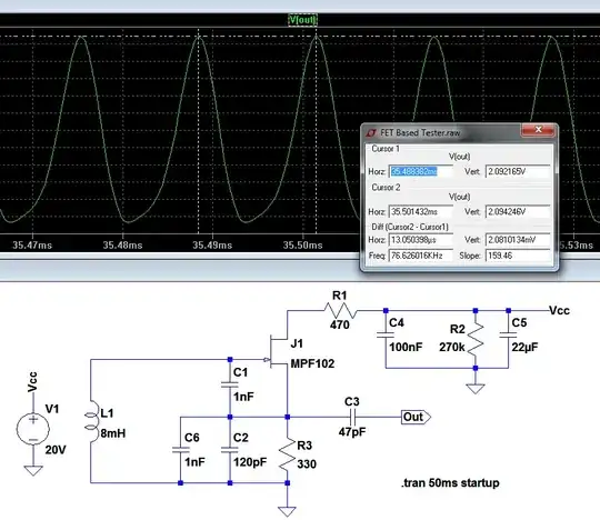
A screenshot of the LTspice simulation is shown below. Notice the frequency. By my calculation, this oscillator should be oscillating at a frequency of about 77 kHz. Instead it oscillates at 300 kHz. If I substitute a resistor in place of \$L_2\$, it oscillates at the frequency predicted by the standard formula $$\frac{1}{2\pi\sqrt{LC_t}} \approx 77\text{ kHz}$$

enter image description here enter image description here

I calculated the 250uH \$L_2\$ value using an online calculator and feeding in the specification given by Ko: 330 turns of "ape hair" and 6mm diameter air core.

Clearly, \$L_2\$ is affecting the frequency. I tried a number of "obvious" alterations to the standard formula, such as paralleling \$L_1\$ and \$L_2\$ - but I still didn't get 300 kHz (or near it). So, it was time to develop the transfer function including L2.

This document (Pota) provides a good analysis of the standard CC Colpitts and I used the same methodology.

enter image description here

The AC model I used is given above and is an alteration of the Pota model to include \$L_2\$. The KCL equation thus includes \$L_2\$ and the resulting transfer function is as follows:

enter image description here

and here's the full working using Maxima (the last step combines Vo with Vx/Vi to give Vo/Vi):

enter image description here

When I substituted \$j\omega\$ for \$s\$ and took the imaginary part to zero, I got $$\frac{1}{2\pi\sqrt{L_1C}}$$ which is clearly wrong. One thing I noticed was that the new transfer function includes an imaginary term in the numerator, that wasn't present in the original TF. I'm a little out of my depth with all this stuff and while the insights are plenty, I'm still not at a level to grasp all of this.

So, my simple questions are, where did I go wrong and how do I get the frequency I'm after?
Null
  • 7,448
  • 17
  • 36
  • 48
Buck8pe
  • 1,674
  • 18
  • 44

1 Answers1

1

When you have L2 (250 uH inductor) connecting source to ground, this is the dominant oscillation mode for this circuit. L2, C2 and C6 form a high impedance parallel tuned circuit that has a resonant frequency of 300.775 kHz. L2 (8 mH) is there to bias the gate at 0 V but still allow an AC voltage to appear on the gate via C1.

When you swap out the 250 uH for a 330 ohm resistor you are back to the standard common drain Colpitts oscillator and L1 (8 mH) does indeed become part of the resonant circuit.

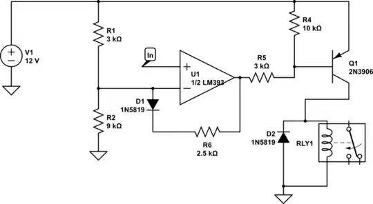
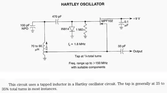
It looks similar to this Hartley oscillator except the 8 mH inductor is replaced with a bias resistor: -

enter image description here
(source: next.gr)

There is also a protection diode in case of excessive gate currents.

Glorfindel
  • 1,245
  • 3
  • 15
  • 20
Andy aka
  • 434,556
  • 28
  • 351
  • 777
  • Can you show how you calculated the resonant frequency (300.775KHz)? When I compute the frequency (using the standard formula) I get 438KHz?? C1=1nF,C2=1.12nF and the now dominant L2=250uH. Formula = 1/2*pi*SQRT(L2*(C1||C2)). – Buck8pe Jan 19 '17 at 15:05
  • C1 has nothing to do with it any more - it just couples the resonant voltage (formed by L2 and the 1.12 nF) to the gate. – Andy aka Jan 19 '17 at 15:27
  • That is absolutely terrific. You wouldn't believe how much figuring I did with transfer functions, etc (not wasted, of course). I'm left wondering how you would tell by looking which (potential) resonant circuit dominates. My intuition tells me that if one tank establishes an oscillation frequency, then the other cannot ring at the same frequency. Is it simply the one with a higher frequency? – Buck8pe Jan 19 '17 at 15:52
  • And just to confirm what I think I've learned from this: it isn't the case that when you have more than one potential tank, the components act together to create a single tank, but rather one of the possible tanks will ring and dominate the others. Have I got that right? – Buck8pe Jan 19 '17 at 15:55
  • If the two resonant points are far apart then sometimes you get no oscillation. I just had the background to recognize it as a common drain hartley oscillator and realized the 8 mH was being used for bias. I don't think there are general rules. Simulating it is always useful then I guess try different combos of L and C and see what shakes through. – Andy aka Jan 19 '17 at 16:11
  • All possible resonant energy-circulating paths will be stimulated by transient energy. Some of the circulating paths will build up the stored energy; others will dampen out. Hence the risks with very fast transistors and ignored parasitic energy storage loops; the gate-stopper resistors often used in power MOSFETS show the eagerness to oscillate. A 1,000pF Cgate MOSFET and 4" wire (approximately 0.1uH) resonates at 50MHz; if the FET channel is short enough to provide power gain, life gets exciting and the FET may overheat with the excess power dissipation. – analogsystemsrf Feb 03 '17 at 15:56
  • interesting but how does this apply to the question or my answer. – Andy aka Feb 03 '17 at 16:17