4

I am working to make flashing LEDs for my airplane model. There are three LED pulse sequences on the picture below where to flash LEDs respectively.

So how do I design a circuit using an astable multivibrator using the IC 555 timer?

How do I design resistor and capacitor values?

Enter image description here

try-catch-finally
  • 1,254
  • 3
  • 19
  • 37
Ajas
  • 77
  • 3
  • 7
    XY problem I'm afraid. – Andy aka Jan 13 '17 at 15:10
  • 1
    You really need to provide the full spec: http://utcaerospacesystems.com/cap/systems/Interiors%20Documents/Lighting%20Systems/06%20Anti-Collision%20Lights/06_0010%20LED%20Anti-Collision%20Lighting%20System%20A320.pdf – jonk Jan 13 '17 at 18:06
  • There, for example, it says that the red LED beacon light operates at "20 ms – 200 ms (20 ms when dimmed by Power Supply)" and this differs significantly from the "Flashing sequences and synchronization" chart, which appears to show 100 ms. – jonk Jan 13 '17 at 18:07
  • I dont think that the 555 timer would get FAA approval .The 555 timer is in www.badbeetles.com .There are other ways. – Autistic Jan 14 '17 at 07:58
  • Andyaka's "XY problem" comment means that you are asking about one thing (Y) but want an answer to another (X). This implies that Andyaka thinks that there is a better way to make these than an electrical circuit. (Unfortunately the "X" question wouldn't be on-topic here.) – wizzwizz4 Jan 14 '17 at 20:12

2 Answers2

20

The granularity of the light sequence suggests a 555 oscillator period of 0.1 seconds (10 Hz). From there, it is a matter of counting and decoding:

schematic

simulate this circuit – Schematic created using CircuitLab

glen_geek
  • 23,591
  • 1
  • 22
  • 50
  • 3
    +1 Although I would certainly use a micro as Olin suggests, this is a nice answer. OP: If it's not obvious, you could use 3/4 of a quad NOR for the two gates shown, so two 14/16-pin and one 8-pin package. – Spehro Pefhany Jan 13 '17 at 15:58
  • 2
    I would use two diodes and a resistor for the OR, two gates of a 4093 for the AND, and one of the remaining gates for the oscillator to eliminate the dreaded 555. A microcontroller is only an easy solution if you've already climbed the learning curve. Although a PICAXE 08M would do the job without much learning. – nekomatic Jan 13 '17 at 23:20
17

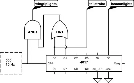
The obvious answer here is to not even try to do this with evil 666 555 timers. You want three signals that need to be kept in phase, and one of them is a double pulse. While this could eventually be accomplished with a mess of 555 timers, it is actually quite simple to do in firmware. All you need is a micro with 3 outputs. Even the tiny PIC 10F200 can do this job.

It looks like everything happens on a 50 ms boundary. Set up a 50 ms tick, then walk thru 20 consecutive states triggered by the tick. This is very easy. Or, you have a array with 20 entries of 3 bits each. Each 50 ms tick, you advance the array index, wrapping from 19 back to 0, then output the three bits to the three output pins.

Olin Lathrop
  • 310,974
  • 36
  • 428
  • 915