1

I have a circuit that must provide PWM to a motor which is expansive in current (around 1.2 A for 4.5V). For the moment I use 100% duty, but I cannot reach the same efficiency as the one I get when I plug the motor directly on the batteries (3x1.5V = 4.5V).

The circuit I used firstly is this one :

+12V ---------+---------+
              |         |
             / \        |
             |M| motor ---  1N4001
             \ /       / \
              |         |
              +---------+
              |
            |/
CTL -/\/\/--|    2N2222 NPN
      1k    |\>
              |
             ---
              -

but then I cannot reach enough voltage so I made a Darlington transistor :

enter image description here

and I replaced the transistor of the first picture by this one. But the current was still under what I wanted (around 0.6A while I want 1.2A), so I tried to put two Darlington transistors in parallel :

+12V ---------+---------+
              |         |
             / \        |
             |M| motor ---  1N4001
             \ /       / \
              |         |
              +---------+-----------+
              |                     |
            |/                    |/
CTL -/\/\/--|         CTL -/\/\/--|    <-- Darlington
      1k    |\>             1k    |\>           
              |                     |           
             ---                   ---        
              -                     -                 

(each "transistor" here is made with two 2N2222A transistors)

But the current stays at around 0.3-0.6A... Why the current isn't added to provide me 1.2A, but stays at the same level as before ? Is their any other way to proceed to reach 1.2A with 2N2222A transistors ?

Thank you in advance.

tobiasBora
  • 111
  • 3
  • First, you're going to have continuous frustration trying to distribute the current between multiple 2n2222 transistors for this amount of load. You are partially on the right track to use a darlington arrangement, but not with this transistor as the main driver. Second, if ever there was a good time to make the jump to using a power MOSFET design, this is it. Only a MOSFET will maximize the power to your motor circuit. And if for some reason your control voltage is too small to control the MOSFET gate, you can always use a transistor there. – Randy Jan 12 '17 at 01:12
  • Use the first circuit, get a transistor with a higher Hfe. Darlingtons are on the right track. – Bradman175 Jan 12 '17 at 03:51
  • increase the mechanical load on the motor. – Jasen Слава Україні Jan 12 '17 at 06:30
  • @Randy : The only MOSFET I have is the IRFZ44N, but the result are not really better... Are 3.3V in input, and 4.5V for the motor enough? – tobiasBora Jan 12 '17 at 10:13
  • @Bradman175: Do you have any good model of transistor ? I'm a bit lost in all the options. – tobiasBora Jan 12 '17 at 10:13
  • @Jasen : I'm not sure to see what you mean, could you please precise ? – tobiasBora Jan 12 '17 at 10:14
  • @tobiasBora TIP112 is an example but you should go on digikey or element14 or mouser and go into the bipolar transistor category and search for transistors with a high hFE like maybe over 500hFE. By the way, 2N2222A has HORRIBLE hFE of around 80hFE. – Bradman175 Jan 12 '17 at 10:39
  • @Bradman175 : Ok thank you. But I'm not sure to see why hFE is important here, since anyway the transistor works in saturated mode. Isn't it supposed to be the maximum current which is important ? – tobiasBora Jan 12 '17 at 11:28
  • I mean maybe it's not the transistor limiting the current. – Jasen Слава Україні Jan 13 '17 at 01:18
  • @tobiasBora Well as I believe, hFE is what sets the maximum allowable current. – Bradman175 Jan 13 '17 at 03:46
  • Are you by any chance having the current limited by the power supply? What voltage do you measure across the motor while it's running? – pjc50 Jan 13 '17 at 16:21

1 Answers1

2

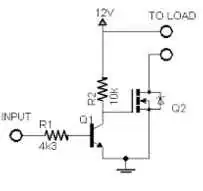
It sounds like you want to be able to control the 12V motor with a low voltage (your comment mentioned 3.3 to 4.5V), and you also want to eliminate the lost motor voltage that is unavoidable with a transistor or darlington pair. I suspect you also need to consider the current capability of your control circuit. This certainly is an ideal time to consider a MOSFET, to ensure maximum efficiency (least lost voltage) driving the motor, but the low control voltage means you'll need a second transistor to act as a voltage amplifier/switch. Since you mentioned having an IRFZ44N, which is an N-channel mosfet, I'd suggest a circuit like this, using the IRFZ44N for Q2. The 3.3V should have little trouble driving this circuit, even if its just a low power microcontroller I/O pin. That MOSFET has some internal protection, but since the motor is inductive, it still would make sense to keep that reverse blocking diode across the motor. You didn't mention having a transistor available, but you should be able to find a small common NPN transistor like a 2n2222 for less than a buck. (your local radio shack currently sells a package of 15 of those for about $3).

enter image description here

(Note I edited this post to use an NPN transistor. I intended a different circuit using a PNP for Q2, but copied the wrong graphic to the post. SORRY)

Randy
  • 3,205
  • 3
  • 21
  • 38
  • The answer mentions PNP but Q1 is NPN, is the schematic wrong? – Krista K Apr 08 '20 at 14:34
  • 1
    Darn it! You're right @ChrisK! I don't know how this sat here so long with that error! The circuit is fine using an NPN as you mentioned. Originally I had a similar but different circuit in mind which used a PNP, but I just edited my text to match the graphic. Thanks for pointing this out! – Randy Apr 15 '20 at 20:17
  • Please note that with your original circuit a high CTL signal would switch your motor on. With this circuit the NPN transistor inverts CTL so your motor will run when CTL is low and not run when CTL is high. That's a minor thing to resolve in software, assuming you are using a microcontroller. Also the body diode across Q2 is not in the same location as a flywheel diode and your 1N4001 is essential for the Q2 to survive. – Ken Mercer Aug 15 '23 at 02:08