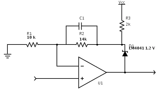
I am wanting to build a custom power supply for myself, and am having trouble understanding how to drive the adjust pin with a microcontroller.
The datasheet for it is here: http://www.ti.com/lit/ds/symlink/lm117.pdf
The issue is that I can make a pseudo? DAC with a low pass filter to get 0-5 volts from my PWM output, however Vout is formed by \$1.25+V_{adj} \$ , meaning, I can only get 1.5-6.5 (or 0-5 if negatively offset) with my solution as is.
My questions are: How do I offset -1.25V? A negative regulator (i.e. LM337) seems a little overkill, however I have never seen a solution with my own eyes and it could be very normal. Are there any quick ways you can think of to offset it?
And more importantly, how do I drive the ADJ pin from ~0-12V if my uC can only output 0-5 with PWM? Is there an indirect method of doing this? A simple building block I can place in between to map this range?
I am quite open to alternatives, however fixing this has piqued my interest and there are not many similar adj. regulators available to me (LT3080 with ~0 offset not available on Mouser at the moment)
