2

I'm helping a friend make a 48 inch hot-wire foam cutter. He would like it to be as economical as possible, so I'm giving him two 15V 1.1A wall wart power supplies that I have sitting around.

I don't think the voltage will be enough to heat such a long wire.

Is there any problem with wiring the output of the two wall warts in series to obtain a 30V output?

Mark Harrison
  • 10,419
  • 27
  • 68
  • 95
  • 2
    Yes, the resistance of the wire is important. Hopefully you are not shorting it out with a copper wire, you should always determine how much current the wire will draw (I = V/R) and ensure it is below the ratings of your power supplies. – Transient Mar 10 '12 at 06:36
  • My guess is 15v is more then enough... Your current capacity may be the issue... Really your choice of nichrome wire is critical, as that determines the resistance. If your doing this with copper wire, you are destined to fail. – MadHatter Mar 17 '20 at 17:50

2 Answers2

2

To answer your question: if the wall warts are not grounded and are isolated from the mains then there should be no problem connecting them in series. I even connected a couple of PC power supplies in series, just made sure to connect them to ungrounded outlets.

Now, will ~30W be enough to heat the wire? Also, you should measure the resistance of the wire and find out what voltage and current it needs, because it may be that it has lower resistance so you would need to connect the wall warts in parallel to get 15V and 2A, but you shouldn't do it, since connecting two power supplies in parallel can lead to problems.

Pentium100
  • 6,550
  • 3
  • 32
  • 39
  • 1
    "just make sure to connect them to ungrounded outlets" -- sounds like a recipe for disaster. – nibot Mar 11 '12 at 20:48
  • @nibot, not really. In the previous place where I lived I used a PC connected to an ungrounded outlet for many years (all outlets in that flat were ungrounded). While PC power supplies leak some current if you touch the case and something grounded, the current is quite small, so I saw no problem in putting two power supplies on top of each other (with a couple sheets of paper between them) and connecting them to ungrounded outlets to get +-12V. – Pentium100 Mar 11 '12 at 23:50
  • The part that is unsafe is suggesting something that will only work when plugged into an ungrounded outlet. The user forgets, uses a different outlet, ... – nibot Mar 12 '12 at 09:16
  • 1
    -1: This answer is dangerous. – nibot Mar 12 '12 at 09:16
  • 1
    @nibot - the vast majority of wall warts (that I have seen) are not grounded, so they can be plugged into any outlet with no problems. Also, my setup with the PC power supplies was temporary, if I was planning o use them like that for a long time, I would have disconnected the grounding wires inside the PSUs. – Pentium100 Mar 13 '12 at 00:12
  • 1
    There's a difference between an appliance that is not grounded (no ground prong), and one that *requires* being plugged into a non-grounded outlet (i.e. has ground prong but requires that it not be connected). The latter strikes me as totally unsafe in the most negligent possible way. Unless I misunderstand your meaning. – nibot Mar 13 '12 at 07:31
  • 1
    Also: "A temporary solution is the most permanent kind." – nibot Mar 13 '12 at 07:33
  • @nibot Wall warts usually do not have ground pins. Since the OP wants to use wall warts that would be OK. I used ATX power supplies. Unlike wall warts, they have ground pins, so I made sure not to connect them. As for "temporary" - I used that setup maybe a couple of weeks at most. When I need temporarily >12V now I just connect a bunch of old SLA batteries in series instead of using PC PSUs. – Pentium100 Mar 13 '12 at 08:37
  • Sorry, -1: the answer doesn't address any safety concerns. Might the power supply output be internally grounded? Who knows? When the comments talk about "having a ground pin", does this mean the wall-connector or the output connector? Maybe in some countries the wall-connector earth pin is optional, and that's what it means - not the case in UK at least, where the earth pin on the wall-connector is required to activate the socket. Seems ambiguous, un-localized advice, seems very unsafe... – SusanW Aug 09 '19 at 10:39
  • Not all outlets(even in the UK, BTW) have three contacts. And I guess UK wall-warts are different, but here in the US, 99% of all wall warts are 2 prong and the output is isolated from mains either by transformer or transformer/optocoupler. – GB - AE7OO Feb 19 '20 at 14:51
0

Is there any problem with wiring the output of the two wall warts in series to obtain a 30V output?

As stated by Pentium100 it depends on the kind of PSU (SMPS, Transformer + (linear) regulator, ...) and how they are built internally.


But since I've stumbled over this problem recently I wanted to offer my ...

"How to connect several SMPS in series with some safety features."

schematic

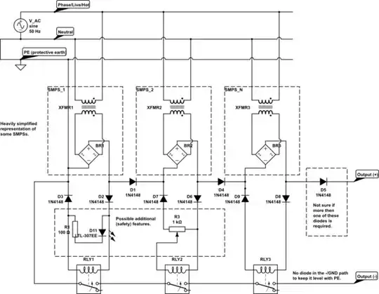
simulate this circuit – Schematic created using CircuitLab

I didn't test this circuit as shown. So far I've only combined an earthed 20V 4,5A laptop SMPS with a floating 32V 2A printer SMPS to supply ~51V (max 1,5A) to a PoE network switch. This didn't work until I put a diode between the two PSUs, presumably because at power-on the PoE switch behaved like a short circuit and the laptop PSU's protection kicked in with -32V across its terminals (see linked questions below). I'm not exactly sure why the diode helped but it did.

Some Notes:

  • At maximum one of the PSUs may be grounded/earthed. Otherwise the PSUs would short circuit each other.
  • The relays ensure that the output voltage is only switched on if and when all single PSUs are working.
  • The LED next to RLY1 is just an idea of an indicator light which shows this PSU to be working.
  • The potentiometer connected to RLY2 is supposed to work as a voltage divider to keep the relay from switching on to early while the PSU is still ramping up.
  • one could even ad circuity to only allow the relays to engage in an individual voltage range for each PSU.
  • The final output voltage is $$ U(out) = V_0 + V_1 + ... + V_n - x*0,6V $$ with x being the number of diodes in the current path (don't count the relay diodes).
  • The maximum current is limited by the PSU with the lowest current capacity.

Id like to post this answer here "Connecting switch-mode power supplies in series to increase voltage" but that one is locked and the other possible questions fit even less:

Limer
  • 239
  • 1
  • 5