2

I would like to rephrase this previous question, but with regard to comparators. I can't decide if a comparator is a digital or analogue device, but I realise that digital devices might be bypassed differently from analogue ones. Clearly the slew rate of a comparator output is way faster than an op amp.

For example, I have a LT1011A - Voltage Comparator in my hand. If I wanted to use it in a comparison circuit at up to say 8 MHz, how would I bypass it's power supply? The datasheet only gives an example of a hysteresis circuit, and I don't want hysteresis. Linear Technology suggests 100nF + 2uF Tantalum in that example.

Paul Uszak
  • 7,327
  • 5
  • 37
  • 69

2 Answers2

2

Bypassing is even more important if you don't have hysteresis. I would tend to use a single 1uF ceramic cap on each supply unless the comparator is switching a particularly nasty load.

The LT1011 is not a particularly fast device (250ns), but it does have high gain.

Spehro Pefhany
  • 376,485
  • 21
  • 320
  • 842
  • Sorry for the unvote but I'm not convinced. I've been looking at this and every single person has a different opinion. The key word being *opinion*. Electronics /mathematics is not really an opinion based art form, but some type of science. I don't see any science in the various opinions across the Interweb. Specifically, I see no formulae in deriving the bypass capacitance whatsoever. Search this forum to confirm this for yourself. All I read is "I do this...", "I would tend..." and "you should always..." Nothing concrete or formulaic. Quantify a *nasty* load for example... – Paul Uszak Jan 05 '17 at 22:21
  • 1
    @PaulUszak I could explain how to do it but it would not be particularly useful to most of those seeking such an answer. There really is not a simplistic formulaic approach that uses available information from data sheets etc. if you are willling to model the circuit very accurately (using field solvers and not just SPICE) and determine the way the internals of a chip really can behave (in the worst case, not just a quick measurement or pulling a number off the datasheet) -maybe you can use a 10n or a 100n (or 33.5n) rather than 1uF. – Spehro Pefhany Jan 06 '17 at 03:55
  • 1
    @PaulUszak (cont'd) but there is not really any engineering incentive to do that in ordinary cases such as your example. Customers typically want reliable product designs, not to turn the design process into a PhD thesis. As you have noted, in some respects design really is an art. Consult books on noise on EMI and noise for much, much more. – Spehro Pefhany Jan 06 '17 at 04:01
1

Fresh out of school, decades ago, a LM111 kicked my butt. Used as the decision maker for a binary-search successive-approximation ADC, that comparator always oscillated during the final few decisions, where overdrive was low. My boss simply had his senior-tech add a few milliVolts of hysteresis, and the 8-bit high-rel rad-hard ADC was shipped/launched/maybe still in orbit.

Problem? I don't recall an Ground Plane being used. And tiny surface mount caps were not in the allowed BillOfMaterial. And the LM111 have much more gain than most comparators of that time. And the LM111 has an output stage with lots of surge current draw, causing the rails to bounce around.

By the way, this TI datasheet www.ti.com/lit/ds/symlink/lm311-n.pdf devotes an ENTIRE PAGE on how-to-stop-oscillations of the LM111.

My conclusion? THE TYPE OF CAPACITOR MATTERS VERY LITTLE. The GND system, to which the +VDD and -VDD caps will be tied is the Key. Use a GND plane, use surface-mount caps, use small package so the lead inductance is low and any ringing will be fast; ensure output logic traces come nowhere near the Pin- and Pin+ input signals and components; keep the source resistors LOW, so Efield coupling from output to input has the low-value R to shunt the injected current.

Additionally, be sure to cleanly reference the input signals to the GND plane, near the comparator. Capacitors from Pin- and Pin+ to the GND plane achieve that.

[edit] Do not use 2 caps in parallel, because you now have a C+L+C PI resonator. You must dampen it, or the VDD of your comparator will ring at HIGH FREQUENCIES.

schematic

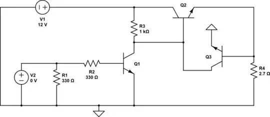
simulate this circuit – Schematic created using CircuitLab

analogsystemsrf
  • 33,703
  • 2
  • 18
  • 46