-2

I'm trying to understand 7 segment display, In the picture below there is a resistor for the GND pin of the 7-segment display, My question is why it needs a resistor?

Because the other display pins doesn't have resistors, Is it correct to assume that the resistors are embedded in the component?

Thanks.
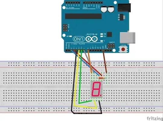
http://circuitdigest.com/sites/default/files/circuitdiagram_mic/Arduino-7-Segment-Circuit.gif

Nick Alexeev
  • 37,739
  • 17
  • 97
  • 230
Kikapi
  • 41
  • 5
  • 1
    It must be a common cathode display and the 220R is limiting the current through all the segments rather than putting individual resistors is each segment and connecting common cathode directly to ground. – JIm Dearden Dec 30 '16 at 13:26
  • 3
    First thing I saw was a silly cartoon, so -1 immediately. We do electrical engineering here, which means we communicate circuit with *schematics*. Closing, since I'm not going to look at this joke to get the circuit. – Olin Lathrop Dec 30 '16 at 14:42

1 Answers1

3

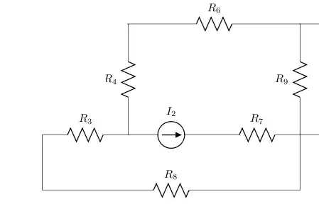
If I read this right, the schematic would look more or less like this.

schematic

simulate this circuit – Schematic created using CircuitLab

This works as long only one LED is powered at the same time. You could just multiplex them.

If you want to power severals at the same time, they will not shine with the same brightness depending on the number of lit LEDs.

You might want to check This question

  • You could remove that resistor and ground directly, but then you would need 8 resistors for each LED on top. – Nazar Dec 30 '16 at 13:37
  • Yes, 8 resistors for each LED on top is the correct way to build this. Using a single resistor on GND is much simpler and safe with the mentioned drawback that the brightness depends on the number of segments being on. – Goswin von Brederlow Jan 23 '18 at 11:59