0

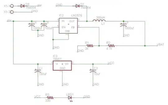
I am designing a SIM900 schematic so before going further I thought of verifying the schematic first. I will using SIM900 with PIC18F2520. So to power the SIM900 and Microcontroller, I am using LM7805 for MCU and LM2576 for SIM900. Following is the circuit:

enter image description here

LM2576 o/p 4.1v is for SIM900 & LM7805 o/p 5v is for MCU

SIM900 Circuit:

enter image description here

Explanation:

PWRKEY: PWRKEY is connected with a push button which when pressed will connect this pin to ground, in order to start the power on scenario of module.

UART: TX RX lines are connected to RX TX of the MCU.

NRESET: connected to a push button to reset the module.

VRTC: I am not using any RTC function so just connected a 4.7uF cap.

NET & STATUS: Connected led's to these pins to show the status and network of the module.

Apart from the above schematic, is there any recommended circuit which I am missing in the circuit.?

Do I need a voltage level shifter between TX RX of SIM900 and TX RX of MCU.? I initially used a breakout board of SIM900 and tested it with the MCU, it was working fine without any external circuitry for voltage level shifter.

Is there anything which I am missing in the circuit. Any suggestions would be very helpful.
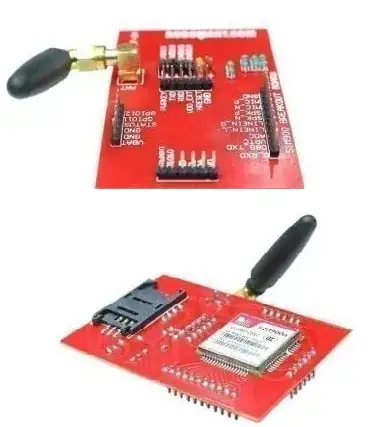
Breakout board: enter image description here

S Andrew
  • 621
  • 10
  • 29

1 Answers1

3

SIM900 Serial interface runs on 2.8 V logic levels, PIC runs on 5 V so you are definitely need level shifting. You did not provide a link to that break-out board but I am sure that there must be some level conversion circuit on that.

From application note.

Please note that the UART level is 2.8V, if the level is not matching, a level shift circuit is needed.

Bence Kaulics
  • 6,353
  • 12
  • 33
  • 60
  • Can you give me a link for that circuit – S Andrew Dec 20 '16 at 14:13
  • There are plenty of them on this site, do a search please. – Bence Kaulics Dec 20 '16 at 14:29
  • @SAndrew I have used dedicated ICs but simple circuits with some MOSFET will do the work. – Bence Kaulics Dec 20 '16 at 16:12
  • Thanks. I will definitely use level shifting. But actually when I did this on breadboard using breakout, I didnt used any level shifting and thats why I got confused. I have added a link to that breakout in question. – S Andrew Dec 21 '16 at 04:32
  • Hey I studied about the level shifting and I found out that its not that much complex. I found this [document](http://simcom.ee/documents/SIM900/SIM900_Serial%20Port_Application%20Note_V1.03.pdf) page 7 where they have described level shifting using transistor which looks best for this problem. Also found this [link](http://www.edaboard.com/thread327975.html) where they have discussed that using [voltage divider](http://www.edaboard.com/attachment.php?attachmentid=112109) circuit is also enough. Which one should I go with.? – S Andrew Dec 21 '16 at 05:13
  • 1
    You can try this IC: http://www.ti.com/lit/ds/symlink/txb0104.pdf – Adam Calvet Bohl Dec 21 '16 at 06:09
  • 1
    This alternative is also fine and simple: http://electronics.stackexchange.com/a/196466/123923 – Adam Calvet Bohl Dec 21 '16 at 06:12
  • @SAndrew Yes, it is the cheapest and easiest way to go with transistors. Also unfortunately the supplier of the breakout board does not include schematic so I could not check the level shifter. But I am sure that there is one, probably they go with transistors as well. – Bence Kaulics Dec 21 '16 at 08:17
  • @AdamCalvetBohl Thanks that IC is also best for this. But unfortunately its not available near by me so I'll go with transistor solution. – S Andrew Dec 21 '16 at 08:43
  • @BenceKaulics Apart from the level shifter, is my power circuit design good for this purpose as I am using two regulators, one for MCU and one for SIM900. What other things I need to keep in mind while designing its board layout. – S Andrew Dec 21 '16 at 08:47