2

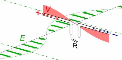
I cannot understand following wikipedia illustration:

dipole antenna animation

It shows the antenna at right angles to the direction of travel of the EM wave. The wavelength is measured in the direction of travel. So why does the relative length of antenna to wavelength matter?

phuclv
  • 458
  • 4
  • 19
fadedbee
  • 994
  • 9
  • 24
  • 1
    It matters in the sense of efficiency, how good the antenna will be at capturing power from that EM wave. When longer or shorter than a certain optimum length the antenna will still work **but** it will be less sensitive and effective. For a transmit antenna for example, less power will be radiated as waves and more power will be reflected back into the amplifier driving the antenna, this power is then converted into heat and lost. Also read: https://en.wikipedia.org/wiki/Electrical_length – Bimpelrekkie Dec 15 '16 at 14:35
  • @FakeMoustache Thanks, I've read the link, but I'm particularly asking about the issue of the antenna length being at right angles to the wavelength. – fadedbee Dec 15 '16 at 15:09
  • @FakeMoustache If it weren't for the fact that the speed of electricity in the antenna was only 0.7-0.9c, I would have guessed that is was just a simple matter of the antenna being "tuned". I would have expected the quarter-wave antenna to be 10-30% shorter than a quarter of the wavelength, to resonate most efficiently. – fadedbee Dec 15 '16 at 15:14
  • 1
    The answer to that is similar, all antennas have a certain sensitivity depending on their direction, see http://electronics.stackexchange.com/questions/273932/what-does-the-radiation-from-an-antenna-look-like/273934#273934 so if the waves do not "hit" the antenna in the optimum direction, the wave will be still be picked up but with less efficiency. – Bimpelrekkie Dec 15 '16 at 15:15
  • 1
    *speed of electricity in the antenna was only 0.7-0.9c* where did you learn this from ? As far as I know the wavelength does not change between air or a conductor. – Bimpelrekkie Dec 15 '16 at 15:17
  • @FakeMoustache https://www.quora.com/Does-electricity-travel-at-the-speed-of-light says 0.7-0.9c and 0.5-1.0c. https://en.wikipedia.org/wiki/Speed_of_electricity says 0.5-1.0c. I shouldn't believe everything I read on Wikipedia... – fadedbee Dec 15 '16 at 15:24
  • The speed of electrons moving is something different that the speed of a wave. A rubber duck floating in a pond moves up and down with the waves but the waves themselves move at an entirely different speed. – Bimpelrekkie Dec 15 '16 at 15:31
  • @Bimpelrekkie the moving speed of electrons is very slow, on the order of 0.1-1mm/s in a metal wire. The speed of electricity is different, which is [0.5c-0.99c](https://www.quora.com/What-is-the-speed-of-electric-current-If-I-switch-on-a-light-how-will-I-know-how-much-time-it-would-take-for-the-light-to-glow). The speed in a coaxial cable is [only ~80% speed of light](https://en.wikipedia.org/wiki/Velocity_factor). Wavelength definitely changes depending on the environment, that's how refraction happens – phuclv Jun 30 '18 at 17:03

2 Answers2

5

So why does the relative length of antenna to wavelength matter?

A monopole antenna (for instance) can be "short" and it will pick up a signal that is proportionately smaller AND look like an impedance that is highly capacitive to the receiver. The "resistive" part of the signal will also be very small too: -

enter image description here

Picture taken from here

This is a good thing for crystal radios because at (say) a length of 0.05\$\lambda\$ it can reactively tune with a coil and produce a decent Q factor in order to give good selectivity in the crystal radio.

On the other hand, for a transmitting antenna, this is problematic because you have to do two things: -

  • Counteract the capacitance (about 1000 ohms at 0.05\$\lambda\$) with a series inductor in order to be able to drive a decent current into said antenna
  • Drive a really low value resistor (the transformed impedance of free space at the electrical terminals of the antenna). It's also hard to find sub-1-ohm coax!

So, transmitting antennas are chosen to have a length that makes the electrical interface simpler. For instance, at 0.25\$\lambda\$ the impedance is purely resistive at about 37 ohms. You could even choose a length that is a bit short of 0.5\$\lambda\$ and get a resistance of over 2000 ohms with no reactive part.

If you go to bigger antenna lengths then you get a repeated pattern: -

enter image description here

Picture taken from here

The base of the graph is in MHz with a quarter wave being at 2.5 MHz. The reactive part of the impedance is blue and the resistive is red with both being in ohms along the y-axis. There are some discrepancies in the amplitudes between the two pictures but this isn't the point - the point is that antenna length affects impedance greatly and it steps and repeats as you go from an electrically short antenna to an electrically long antenna.

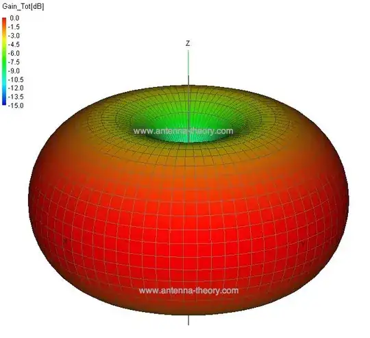
Regarding the antenna pattern, a dipole looks like this with the antenna vertical and at the centre: -

enter image description here

Picture taken from here

Andy aka
  • 434,556
  • 28
  • 351
  • 777
  • No mention of the right-angle issue. – fadedbee Dec 15 '16 at 15:25
  • @chrisdew my final picture attempts to address that - it tells you that the most sensitive part of a simple dipole antenna is at right angles to the "line" of the antenna but it's difeerent for other antennas - it's a big subject. – Andy aka Dec 15 '16 at 15:28
  • Yes, I understand why the antenna needs to be in direction of the electric field component of the em wave. What I don't have an intuitive understanding of, is why an antenna resonates, *unless* the speed of electricity in the antenna is almost the same as the speed of light in air (i.e. the speed of the em wave). In that case it's like a quarter-wave one-closed-end pipe, which I can understand. – fadedbee Dec 15 '16 at 16:03
  • Where was this in your original question? I wil answer it but i will point out that this was not mentioned in the original question. Basically it transforms impedance from (say) the 37 ohm electrical impedance of a qtr wave monopole to the impedance of free space. Speed increases as the impedance of the antenna changes from the electrical driving point to the tips of the antenna. – Andy aka Dec 15 '16 at 16:33
  • Are the reducing heights of the input resistance peaks with length due to greater attenuation? – Lewis Kelsey Dec 10 '21 at 12:49
  • @LewisKelsey as the length of the antenna drops, the effective radiation resistance of the antenna drops. This translates to a lower voltage received but the same power received. Of course, this might need some form of impedance translator to recover the voltage with minimal losses. I'm talking about receivers mainly here and, although the term "radiation resistance" appears to apply to a transmitting antenna, it equally applied when receiving. – Andy aka Dec 10 '21 at 13:01
  • As I understand it, the input resistance is how the open circuit is seen at the input. If there were no loss or radiation resistance, it would be 0 resistance for a half wave dipole (quarter wave transformer). I think the incident wave and reflections are attenuated by the loss and radiation resistance and hence it produces a non zero value at the input, seemingly equal to the loss plus radiation resistance. For a full wave dipole, the open circuit should be infinite resistance at the input, but it's attenuated to non infinite value by the radiation and loss resistance – Lewis Kelsey Dec 10 '21 at 13:29
  • OK I hear what you say so now, I'm going to encourage you to ask a formal question on this subject so that others can contribute. Comments are not for extended discussion and you are raising new things that you'd like to be addressed. You also need to be clearer in what you ask/say. Please don't try and fix that here but, when you say this: `the input resistance is how the open circuit is seen at the input` it is meaningless to me what you are talking about. Do this justice and ask a new question please. – Andy aka Dec 10 '21 at 13:55
2

Suppose you have a receiving, dipole, antenna. Ignore the existence of free space around the antenna — ignore that wavelength — and just think about the portion of the electromagnetic field immediately around the antenna. The field exerts a force on the electrons in the antenna, perpendicular to the propagation of the wave (or more precisely, in the same direction as the polarization of the wave). That is where the right angle comes from.

The wavelength of the wave in space is irrelevant, so far, because the antenna elements don't see it, they just see a locally oscillating field.

Now think about what happens in the antenna conductor. There is a force causing the electrons to move (a current). On the other hand, the antenna has ends, and current cannot flow out the end of a wire (outside of conditions that do not apply here).

Consider just the field impinging on some electrons near the middle of the antenna and ignore the rest of the field. They can start to move, and just like any other change in current in a conductor, it propagates, as a wave, along the conductor at a speed close to (but not equal to) the speed of light. When this change reaches one end of the wire, current can no longer flow there, so just like any wave hitting an obstacle it reflects back and reaches its starting point, and there are standing waves within the antenna.

You've indicated that you already understand the idea of sound waves and standing waves in a pipe, so I'll skip going into more detail there. Just note that the proper analogy purely from the perspective of analyzing standing waves is:

  • wire end: closed end of pipe — current node — voltage antinode
  • middle of dipole: middle of both-ends-closed pipe — current antinode — voltage node

The there is no obvious direct analogy for the interaction of the EM wave since it is spread out along the entire length — it's like you have a series of fans in the pipe, not like an outside pressure wave passing through an opening.

To summarize: the two lengths are similar not because the extent of the wave in free space maps somehow to the extent of the wire despite being at right angles, but rather because there are two wave phenomena of the same frequency and almost the same propagation speed.
Kevin Reid
  • 7,444
  • 1
  • 25
  • 44