I have a function which turns on a LED by setting PB1 to HIGH. The light from the LED is barely visible. If I set PB1 to HIGH in my main function the light from the LED is as bright as it should be.
It makes no sense to me since it's just changing a value, which is either 0 or 1. I must be missing something extremely obvious, but what could it be?
Here's some background information:
- The LED is connected in series with a resistor so it's not being shorted
- I have tried the two different codes attached multiple times to make sure the problem is reproduced every time
- I have tried to use a different pin to rule out that there is something wrong with that specific pin
Edit: Added some more information and tags
- Chip: ATmega328-PU
- Programmer: AVRisp MKII
Here's the code with the pin set in main:
#include <avr/io.h>

int main(void) {
    DDRB |= (1 << PB1);

    PORTB |= (1 << PB1);

    while(1) {
    }

    return 0;
}
And here's the code where the pin is set in a function:
#include <avr/io.h>

void turn_on_led();

int main(void) {
    DDRB |= (1 << PB1);

    turn_on_led();

    while(1) {
    }

    return 0;
}

void turn_on_led()
{
    PORTB |= (1 << PB1);
}
Here is the makefile:
main:
    avr-gcc -g -Os -Wall -mmcu=atmega328 -c ../src/example.c

elf:
    avr-gcc example.o -o example.elf

hex:
    avr-objcopy -O ihex example.elf example.hex

dump:
    avr-objdump -h -S example.o > example.lst

upload:
    avrdude -p m328 -c avrispmkII -P usb -U flash:w:example.hex

clean:
    rm -f *.o
    rm -f *.hex
    rm -f *.lst
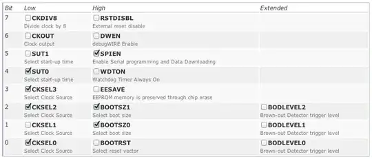
Fuse setting:
avrdude: Device signature = 0x1e9514
avrdude: safemode: lfuse reads as E2
avrdude: safemode: hfuse reads as D9
avrdude: safemode: efuse reads as 7
Fuse setting input in a fuse calculator to show individual bits:
Disassembly of setting pin in main:
example.o:     file format elf32-avr

Sections:
Idx Name          Size      VMA       LMA       File off  Algn
  0 .text         00000006  00000000  00000000  00000034  2**0
                  CONTENTS, ALLOC, LOAD, RELOC, READONLY, CODE
  1 .data         00000000  00000000  00000000  0000003a  2**0
                  CONTENTS, ALLOC, LOAD, DATA
  2 .bss          00000000  00000000  00000000  0000003a  2**0
                  ALLOC
  3 .debug_abbrev 0000004e  00000000  00000000  0000003a  2**0
                  CONTENTS, READONLY, DEBUGGING
  4 .debug_info   00000082  00000000  00000000  00000088  2**0
                  CONTENTS, RELOC, READONLY, DEBUGGING
  5 .debug_line   000000c2  00000000  00000000  0000010a  2**0
                  CONTENTS, RELOC, READONLY, DEBUGGING
  6 .debug_frame  00000020  00000000  00000000  000001cc  2**2
                  CONTENTS, RELOC, READONLY, DEBUGGING
  7 .debug_pubnames 0000001b  00000000  00000000  000001ec  2**0
                  CONTENTS, RELOC, READONLY, DEBUGGING
  8 .debug_pubtypes 0000001e  00000000  00000000  00000207  2**0
                  CONTENTS, RELOC, READONLY, DEBUGGING
  9 .debug_aranges 00000020  00000000  00000000  00000225  2**0
                  CONTENTS, RELOC, READONLY, DEBUGGING
 10 .debug_str    000000d9  00000000  00000000  00000245  2**0
                  CONTENTS, READONLY, DEBUGGING

Disassembly of section .text:

00000000 <main>:
#include <avr/io.h>

int main(void) {
    DDRB |= (1 << PB0);
   0:   20 9a           sbi 0x04, 0 ; 4

    PORTB |= (1 << PB0);
   2:   28 9a           sbi 0x05, 0 ; 5
   4:   00 c0           rjmp    .+0         ; 0x6 <__zero_reg__+0x5>
Disassembly of setting pin in function:
example.o:     file format elf32-avr

Sections:
Idx Name          Size      VMA       LMA       File off  Algn
  0 .text         0000000c  00000000  00000000  00000034  2**0
                  CONTENTS, ALLOC, LOAD, RELOC, READONLY, CODE
  1 .data         00000000  00000000  00000000  00000040  2**0
                  CONTENTS, ALLOC, LOAD, DATA
  2 .bss          00000000  00000000  00000000  00000040  2**0
                  ALLOC
  3 .debug_abbrev 00000061  00000000  00000000  00000040  2**0
                  CONTENTS, READONLY, DEBUGGING
  4 .debug_info   00000096  00000000  00000000  000000a1  2**0
                  CONTENTS, RELOC, READONLY, DEBUGGING
  5 .debug_line   000000dc  00000000  00000000  00000137  2**0
                  CONTENTS, RELOC, READONLY, DEBUGGING
  6 .debug_frame  00000030  00000000  00000000  00000214  2**2
                  CONTENTS, RELOC, READONLY, DEBUGGING
  7 .debug_pubnames 0000002b  00000000  00000000  00000244  2**0
                  CONTENTS, RELOC, READONLY, DEBUGGING
  8 .debug_pubtypes 0000001e  00000000  00000000  0000026f  2**0
                  CONTENTS, RELOC, READONLY, DEBUGGING
  9 .debug_aranges 00000020  00000000  00000000  0000028d  2**0
                  CONTENTS, RELOC, READONLY, DEBUGGING
 10 .debug_str    000000e5  00000000  00000000  000002ad  2**0
                  CONTENTS, READONLY, DEBUGGING

Disassembly of section .text:

00000000 <turn_on_led>:
    return 0;
}

void turn_on_led()
{
    PORTB |= (1 << PB1);
   0:   29 9a           sbi 0x05, 1 ; 5
}
   2:   08 95           ret

00000004 <main>:
#include <avr/io.h>

void turn_on_led();

int main(void) {
    DDRB |= (1 << PB1);
   4:   21 9a           sbi 0x04, 1 ; 4

    turn_on_led();
   6:   0e 94 00 00     call    0   ; 0x0 <turn_on_led>
   a:   00 c0           rjmp    .+0         ; 0xc <main+0x8>