Ok, this is very simple:
Voltage is relative. You can call anything ground and use it as ground(well, almost).
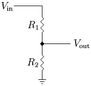
Your voltage divider splits the supply into two equal parts(you could do any parts or even use caps, inductors(not a good idea), tubes, or anything that will give you Vcc/2.
This is called "rail splitting". We need to have a + and - voltage for op amp/analog stuff when we want to be able have negative swings. If we don't our signal's end up only working on the positive half(and generally nothing really works like it should).
Assuming you understand how the resistive voltage divider works and that the middle should be Vcc/2 if the two resistors are the same. The second thing to notice is that we could use the middle of the voltage divider, Vout in your pic, to act as ground(and the gnd in your pic would then become -Vcc/2).
BUT!! There are some problems with this. The resistors limit the total amount of current we can use AND if we use things that pull current from the resistors it will effect the values. So either we have to use very low value resistors, wasting a lot of power, use very efficient devices, or fine some way to provide more current.
This is where you 2nd picture comes in. It is an op amp configured as a buffer. You are missing one key part of the drawing. The op amp has power pins supplied to it. I'm not going to explain how an op amp works but there a plenty of things online.
Anyways, the buffer takes a voltage in and produces the exact same voltage at the output BUT it allows for larger loads. A buffer is also called a UNITY GAIN Voltage amplifier. That is, it doesn't really amplify the voltage but that's exactly what we want. It does this by pulling current from the power pins "adds" it to the output.
So, we have our crappy voltage divider that doesn't work well for much of anything, but we use a device, in this case the op amp, to provide us with more current drive. This way we can drive things like maybe an LED, a motor, or other op amps or whatever with Vcc/2(or whatever ratio we wanted.
The Op amp will be happy to provide a lot of current to those devices if they need it. The resistor voltage divider can't do it and it will screw things up big time.
Realize, all we are doing is BUFFERING the voltage Vout on the voltage divider. You can sort of forget the op amp... it's just a tool to do that. We could have used a bjt, npn, jfet, TL431 or many other things to do it. The point is now we have created a sort of minature power supply with voltages A, (A - B)/2, and B.
Hopefully you got that.
Suppose we had Vcc = 10V, Gnd = 0V then a 1:1 divider gives us Vout = Vcc/2 = 5V!
BUT since voltage is relative(you can basically add any value to all the voltages)... we can also view it as
Vcc = 0V, Gnd = -10V, Vout = -5V.
or better yet
Vcc = 5V, Gnd = -5V, Vout = 0V.
Then to make it even easier we will relabel things to get
Vcc = 5V, Vss = -5V, Gnd = 0V.
Now we have a +- power supply. We got this from a + power supply. But we can now forget we even have a + power supply if we want and just work with the +- supply.
This makes live much easier since lets us shift the signals to be centered at 0V instead of Vcc/2... which is really not that difficult to think about but it is unnecessary.
There are some caveats to this method but there are some very good things on the net that talk about them and I'll leave you to find them when you are ready. Just remember once you get the circuit down, even if you don't understand it fully, you can forget how it works and just think of it as a +- power supply... as if that is what you started with in the first place.... cause really that is what you have created with the voltage divider and you've improved it's power supply ability by using the op amp. you can even make it better by adding more junk to fix things if you want.
AGAIN!!!!
Voltage is relative: This means you can add any fixed constant to ALL the voltages without changing any of the physics.
Labels can be relabeled: You can relabel things all you want as long as they are a permutation(no duplicating them or dropping them). If you want to call rename GND to VCC and VCC to GND you can. Of course this is confusing because it will flip the currents and they won't go in the direction we are used to.. But if you order the labels in terms of voltage you can sort of shift them any direction but not rearrange and it will make sense:
So
..., ] Vcc, Gnd, [Vss, ...
can be shifted
. ..., ] Vcc, Gnd, [Vss, ...
..., Vcc ] Gnd, Vss [, ...
So Vcc became Gnd and Gnd become Vss. (Note, the bracket stuff are labels I've added. The point is, they are ordered in terms of voltage).
For our +- supply
Vcc, Vcc/2, Gnd, -Vcc/2 (Vcc/2 doesn't exist in our original labeling but it's what we want to go to)
can become
Vcc , Vcc/2, Gnd
Vcc/2, Gnd , -Vcc/2
So Vcc -> Vcc/2
Vcc/2 -> Gnd
Gnd -> -Vcc/2
THIS IS EXACTLY THE SAME as when I subtracted 5V from the 10V supply we had. So the methods are the same. The labeling stuff might be more confusing but maybe not.