7

From my work I've had quite a bit of experience with hardware development, but purely from a supervisory role, and so recently I've been playing around with ground up MCU circuit design to try to get a better understanding.

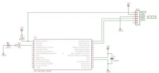
I put the following circuit together to allow me to play around with the MCU registers a bit and it does work - only intermittently.

The LED blinks as intended, then stops for an arbitrary time, flashes again a different number of times, off again etc. There doesn't seem to be any cyclic behaviour to it. It starts working without any external input (i.e. nudging it) so doesn't seem like a loose connection either. I realise the second Vss pin isn't grounded in the schematic, but this didn't help the circuit either when I tried it. Could it be because Vusb isn't grounded? I would have thought this would only affect USB operation.

Schematic

Code:

#include <stdio.h>
#include <stdlib.h>

#include <p18f2550.h>
#include <delays.h>

#pragma config FOSC = INTOSCIO_EC       

#pragma config WDT = OFF                

void main() {

    TRISAbits.TRISA1    = 0;    // Set RA1 as output
    LATAbits.LATA1      = 1;    // Set RA1 as HIGH

    while (1)
    {
        LATAbits.LATA1 = ~LATAbits.LATA1;   // Toggle LED pin
        Delay10KTCYx(25);                   // Delay
    }    
}

Here is the datasheet for the part.

Chetan Bhargava
  • 4,612
  • 5
  • 27
  • 40
njt
  • 291
  • 2
  • 11

2 Answers2

14

Two things:

  1. One Vss pin is not connected. All Vss, Vdd, AVss, and AVdd pins, when present, must be properly connected.

  2. PGM is floating, which is bad if LVP is enabled. That can randomly put the part in programming mode.

Olin Lathrop
  • 310,974
  • 36
  • 428
  • 915
  • 3
    Just to back this up, a year or so ago I had exactly those symptoms with the same part when I left PGM floating. – John Burton Feb 23 '12 at 21:18
  • 1
    Excellent, thanks. PGM with a 10k resistor to gnd solved it. – njt Feb 23 '12 at 22:42
  • 1
    @njt: It's also a good idea to disable LVP in the static configuration unless you're actually using it. – Olin Lathrop Feb 24 '12 at 15:32
  • I've been struggling with an unstable circuit that has been driving me crazy, and although this answer is quite old, it has proven to be the solution to my problem. Thanks a lot! – Merlevede Nov 02 '14 at 01:17
4

Even though you're not using the Vusb pin, it's still a component of the chip you're using. You're not disabling it in code, so you need to comply with the requirements in table 28-5.

Those requirements include a 220nF or greater capacitor between the Vusb pin and ground to make sure that the internal regulator is stable. Note that I said between Vusb and ground, you don't want to short this pin out - It's the output of an internal voltage regualtor. This is unlikely to cause the behavior you're observing, but it's required by the datasheet.

Also, you've failed to connect anything to the Vss connection on pin 8. This might be tied to the Vss pin you are connected to, but it's not guaranteed. They might not be tied together, and half of your IC is floating. It's also possible that you need two pins to reduce the impedance to ground to achieve a certain speed or a certain current sinking capability. In any case,you should also connect this pin to Vss.

To go meta for a moment, you need to understand that the datasheet is like a contract between you and Microchip. Perhaps the Vusb pin would cause problems if you didn't connect it, perhaps it wouldn't, perhaps it would only cause problems when you went to demonstrate it or when you connected something dangerous. You need to consult the datasheet to determine what you are supposed to do with each pin. As you might suspect in a 428 page document, most everything is specified. Each of the other pins will also probably have a specification. It's very common for unused input pins to require a connection to either Vcc or Vss. I'm not a PIC expert, but I think that there are is at least one more input-only pins which is used for other programming and debug modes.

Kevin Vermeer
  • 19,989
  • 8
  • 57
  • 102
  • I thought the cap on Vusb is only necessary when the internal regulator that makes 3.3V is enabled. This is basically the output cap for that regulator, which is something that can't reasonably be put on the die. There is no need for it when the regulator is off, which it is unless the USB module is turned on and in the right mode. You can, for example, tie Vusb to Vcc if they are 3.3V, if I remember right. – Olin Lathrop Feb 24 '12 at 01:51
  • @OlinLathrop - "*which it is unless the USB module is turned on and in the right mode*" - I agree that it's only necessary if the regulator is on, but I'm not sure about the default state. I thought it was on unless you turned it off, and the posted code does not turn it off. – Kevin Vermeer Feb 24 '12 at 05:01
  • @Kevin: I just checked, and it appears you are right. I thought the regulator went on and off together with the USB module, which can be enabled and disabled in firmware at any time. However, it seems the regulator is only controlled by a config bit, which is in the enabled state after erase. So yes, the OP should either provide a proper Vusb cap or disable the USB regulator in the static configuration. – Olin Lathrop Feb 24 '12 at 13:09
  • I'm not sure I follow the theory behind the cap on the Vusb pin, could anyone give a quick explanation? thanks! – njt Feb 25 '12 at 18:17
  • @njt - Inside the chip, there's a linear voltage regulator which has its output at pin 14, Vusb. This regulator senses its output voltage, and adjusts up if the voltage is too low, or down if it's too high. If there's no load, what would ordinarily be a small adjustment would result in large oscillations. If there's a capacitor, these oscillations will be small. Some linear regulators don't need caps for stability, but this datasheet says it needs a 220 nF capacitor. – Kevin Vermeer Feb 25 '12 at 18:47
  • I suggest that you disable the regulator if you're not using it. The config bit is VREGEN in config word CONFIG2L, see table 25-1 on page 286. Write it to '0' to turn it off. – Kevin Vermeer Feb 25 '12 at 18:50