0

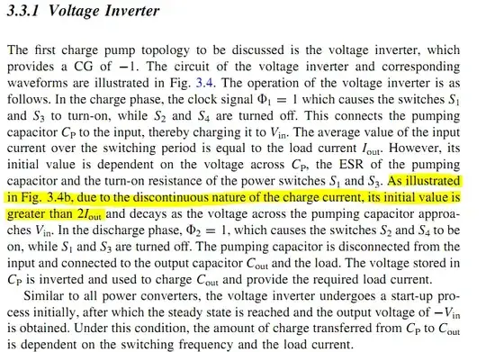
The figure below is a voltage inverter from the book Reconfigurable Switched-Capacitor Power Converters by Dongsheng Ma and Rajdeep Bondade.

Link: Reconfigurable Switched-Capacitor Power Converters - Google Books

Please refer to the text explanation below. What I don't understand is why the initial value of Iin is greater than 2*Iout. Could anyone explain more about the yellow highlighted part?

enter image description here

enter image description here

emnha
  • 1,547
  • 4
  • 34
  • 84
  • The circuit drawing is a bit misleading. The circuit contains parasitic components that are essential for the way it functions but are not described or included in the circuit. So it's for instance impossible to calculate peak currents. In my opinion circuits like this shouldn't appear in textbooks or articles. – joe electro Nov 17 '18 at 07:39

1 Answers1

1

What I don't understand is why the initial value of Iin is greater than 2*Iout

If Vout is -Vin (on average) and Iout is a continuous current taken by the load then, Iin has to be slightly more than double Iout to produce the power input needed to sustain the power required by the load.

The average value of Iin is slightly greater than the average value of Iout. That slight numerical difference accounts for switching/charging losses in the process.


ADDENDUM on charging a capacitor

It seems intuitive that charging a capacitor from either a perfect voltage source or another capacitor should not incur losses. For instance, if 1 farad had 1 volt on it, it would possess 0.5 joules of energy (\$CV^2/2\$). There would also be a charge of CV. Now, if an uncharged 1 farad were put in parallel, you would expect the energy to remain the same but now shared equally between the two capacitors.

If you go down this route, using the energy equation you could expect the terminal voltage to have dropped to 0.7071 volts.

However, if you looked at the charge equation (Q = CV), the voltage must be 0.5 volts. One of them is wrong and it is the energy equation. You just cannot transport charge without incurring losses. There is conservation of charge but not conservation of energy.

You can even simulate this too and get the right answer.
Andy aka
  • 434,556
  • 28
  • 351
  • 777
  • Thanks. Is the Iin waveform above only correct when switches S1 and S3 are not ideal? How about if all components are ideal? – emnha Nov 04 '16 at 05:40
  • 1
    Then you get infinite inrush current. I know this doesn't sound intuitive but the losses remain the same no matter how low the switch resistance is. You can't charge a capacitor from a perfect voltage source without incurring losses unless you use a series inductor. – Andy aka Nov 04 '16 at 09:37
  • So, where does the energy loss go (not capacitor because it is ideal and do not dissipate energy, not on switch because it is also ideal too)? – emnha Nov 04 '16 at 09:49
  • 1
    Try reading this post and I'll also add a little bit at the end of mine: http://electronics.stackexchange.com/questions/29535/energy-in-capacitors/29536#29536 – Andy aka Nov 04 '16 at 09:58
  • 1
    See also this: http://electronics.stackexchange.com/questions/75456/decrease-in-stored-energy-after-connection-of-another-capacitor?noredirect=1&lq=1 – Andy aka Nov 04 '16 at 10:04