2

I'm doing a project with the ATUC256L4U microcontroller, and it will require a USB type A connection. I've never worked with USBs before and the microcontroller datasheet doesn't offer much information on how the hardware should be set up. I'm aware the ATUC256L4U has dedicated USB pins, which I think will handle the necessary pull up resistors, but would the circuit really be as simple as the one below?

I've seen other circuits with protective ICs connected, are these necessary or will the dedicated micro pins handle this?

I'm also not planning on powering the device via the USB, should I still connect the 5V pin to something or just leave it unconnected?

enter image description here

ram
  • 109
  • 1
  • 2
  • 3
  • You have a lot of learning ahead of you. USB is a giant pain in the backside, mostly in software. However, the USB spec is pretty clear about what hardware guidelines should be followed, and generally microcontroller manufacturers have decent application notes on how to physically connect their product. If you don't know whether the the MCU has the pullups integrated, don't assume. Also, any particular reason you're using an AVR32 instead of an ARM? – Brendan Simpson Oct 26 '16 at 15:18
  • 2
    USB type-A connectors are for USB *hosts*. Your ATUC256L4U seems to only be capable of being a USB *device*. Could you clarify your plans here? – brhans Oct 26 '16 at 15:22
  • 1
    ("the microcontroller datasheet doesn't offer much information on how the hardware should be set up. ") This is because most embedded chip manufacturers publish common documents for complex interfaces such as USB ports. Go back to Atmel and search for what you want. I did and there were dozens of USB documents depending on what type of USB Device (HID, CDC, ect) you are trying to make. – st2000 Oct 26 '16 at 15:22
  • And what @brhans said is true, you are using the wrong type of connector. You need a B on a USB Device. As for power, a USB Device does not offer power. So leave the power pin disconnected. But you might have to connect the ground. – st2000 Oct 26 '16 at 15:25
  • Last note, what @BrendanSimpson said is also true, unless you are emulating a USB mouse or keyboard - it is much easier to use I2C or SPI to talk to other hardware. FYI: No one (well hardly no one) writes the USB stack from scratch. They usually get it from the OEM of the processor. There's lots of PDFs on Atmel's site on this. It's that complex. – st2000 Oct 26 '16 at 15:37
  • USB type A PLUGs are used for small USB Devices (such as thumb drives), but USB devices should not use a type A RECEPTACLE which are for hosts. – Tut Oct 26 '16 at 15:48
  • Right, I'll use a type B then. I'm using this chip because I need a high number of PWM channels, and it's got 36. I'm using SPI to actually program & the firmware, but I was planning on using the USB to communicate with the device once it is actually up and running and control the PWM outputs. – ram Oct 26 '16 at 17:02
  • @Tut, actually, the Type-A plug is considered as a very short form of captive cable. As result of this determination, electrical requirements at the plug are the same as at far end of a 5m cable (or whatever the limit is). – Ale..chenski Oct 26 '16 at 21:10

3 Answers3

3

This particular processor, ATUC256L4U, has support only as a USB device, and only at Full-Speed (12Mbps) rate. Therefore, as USB device, it can have either attached cable with Type-A plug, or female receptacle of B-type, either full-size B, or micro-B, since more reliable and sturdy mini-B has been obsoleted and retired by USB.org. Use of Type-A receptacle is incorrect.

The FS mode does not require too much care about board traces as transmission lines. However, depending on type of USB transceivers, a serial resistors (22-27 Ohms) with small caps (10pF) to ground might be helpful to keep the port reliable and ESD protected, maybe even without any extra suppressors.

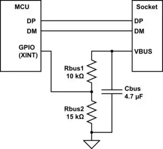
The main concern for a USB-compliant device is what to do with VBUS signal (Vcc on the diagram). One function of VBUS is to supply power to the device (if it does not have its own). But the other important function of this pin is to inform the device that it was connected to a host. If this signal is misused (not used for this purpose), the device will have no means to detect the connection, to assert the pull-up on D+ starting USB connect negotiation (if it has self power). The point is that a good USB device should not source any voltage or significant current on any USB interface pins until it is connected to host and receives valid VBUS. Many older devices would ignore this requirement and pull-up D+ to 3V with 1.5k resistor regardless, thus violating USB specifications.

Many Atmel's MCU do have a dedicated "VBUS_detect" input pin for USB interface. For the ATUC256L4U I couldn't locate this pin right away, maybe more examination is required. If no dedicated pin, a GPIO should be used to provide this functionality.

Ale..chenski
  • 38,845
  • 3
  • 38
  • 103
2

The answer to this mainly depends on whether you need to pass USB certification or not. If not (i.e. this is a personal project), you can probably get away with connecting the DP and DM pins directly to the jack and leaving VBUS unconnected. If you need to pass certification, you'll have to do at least the following:

  1. Monitor the state of VBUS. Only connect the DP pull-up to the line when VBUS is high. The USB module should provide a way to do this. If the USB module doesn't have a dedicated VBUS pin you can use a resistor voltage divider to reduce the 5V to something compatible with your 3.3V IO pins. It's best to use an interrupt-capable GPIO for this.

  2. Have at least 1uF but no more than 10uF of capacitance on VBUS. I've passed certification with 4.7uF so that's what I'll recommend. This is needed to pass the inrush current test. (See also this answer.)

If you don't do these things, you will fail certification.

IO/ESD protection is not necessary for functionality. Whether you want it is up to you.

schematic

simulate this circuit – Schematic created using CircuitLab

Adam Haun
  • 21,331
  • 4
  • 50
  • 91
  • Actually, the VBUS question is not about passing certification or not. It is about following USB specifications or not for connect protocol handshake. Slogan: "no VBUS => no D plus". The certification requirements are for a reason - some OTG hosts can be confused if they see D+ before they assert VBUS. Or, if the host is powered off while this bad device is connected, the D+ pull-up can charge the host to some middle-voltage level via ESD clamps, and the host might fail to power up correctly. – Ale..chenski Oct 26 '16 at 23:32
  • I agree. I was trying to distinguish between a personal project (which might only ever connect to one PC) vs. a commercial project (which has to obey the specs and probably has to be certified to do so). – Adam Haun Oct 27 '16 at 02:06
0

In systems I've been involved with the protective ICs you refer to are usually ESD supressors. I suppose whether you actually need to add protection depends on how robust you want the design to be and how suseptible the part/application is, the downside is that anything on the USB lines will potentially degrade the signal quality.

Check out the application note for your chip here. It looks like you do need the external Rs but you should check the datasheet to confirm.

Whether you need anything else in circuit depends very much on your application; mainly what speed of USB interface you are intending on using and how long you anticipate the signal traces to be. I haven't looked at your proposed micro and am not familiar with it but if you want high-speed (480Mbps) then this is another good resource.

At this speed your layout is likley to be fairly critical I think a good rule of thumb is if your trace length is 1/10 wavelength (I think thats around 6cm at 480Mhz) then you need to consider your signals as a transmission line i.e. matched impedance is required on the PCB as discussed in the articles.

On some designs I have done where we've had several high-speed USB hubs on a backplance with very long trace lengths we've had to use the common-mode chokes as described in the intel app note to get the system to pass EMC compliance testing (it was for emissions in that case).

If this all worries you a little too much stick with full-speed (<12Mbps) and you'll probably get away with anything.

Good luck.

EDIT:

As pointed out your chip doesn't support high-speed so my discussion about the criticality of the layout is not really that important to you. A 0 to 10R, 22pF RC on the signal lines is usually sensible, often times the manufacturer will recommend something like this. I'd always start with the manufacturer recommendations.

SpaceCadet
  • 314
  • 1
  • 5
  • That app note is for the wrong chip. It covers high speed, not full speed. – Adam Haun Oct 26 '16 at 21:22
  • Yeah, I foolishly didn't check what speed the chip runs at before posting. I just assumed it was high, same applies though, you're still supposed to get 90R impedance but as it's only 12MHz transmission line effects only come into play at MUCH longer track lengths. – SpaceCadet Oct 26 '16 at 21:50