6

Problem

I have been working on drives for a while, but one problem that I never seem to be able to really get around is the regeneration that occurs when our PID loop commands a lower speed/torque value while the motor is spinning and I am looking for the 'Aha!' that will guide us.

PWM Method

We generally use a standard 3-phase Space Vector Modulation (SVM) technique, which means that - aside from dead time - there is always a MOSFET that is 'on' in a particular phase. We like it that way as our switches operate most efficiently using this method.

Braking Methods we have Known

I know that this isn't a comprehensive list, but we have considered a few things and I feel that it might be informative to include them.

Brake Resistor

We integrate drives into small motors (P < 200W), so we simply don't have the space for a braking resistor that is large enough to handle the peak powers involved. We have a motor with ~41J when it is rotating at 50krpm that we need to decelerate in ~300ms, which means that the expected peak power is ~136.7W for a short time. Anything on the size order of a TO-220 would be out of the question.

Large Energy-Storage Capacitor

For many of the same reasons that we wouldn't be able to use the resistor, a large capacitor would not work as well. In order to get a 10V rise, we would have to be able to store the 41J directly on the capacitor, requiring ~1F.

Coasting the Motor

"Releasing" the PWM and allowing the motor to coast is OK in some of our applications, but not most.

Shorting the Low Sides of the Motor (Dynamic)

For very fast deceleration from high speed without regeneration, we have resorted to shorting the low-side MOSFETs for a period. This has the unfortunate side-effect of being an uncontrolled deceleration.

Plugging

Effectively, reversing the voltage across the motor. This generates some pretty high currents, but does brake the motor. The problem with this one is deciding under what conditions to plug. We have never deployed this one to production because of the high currents involved and the uncertainty of when the software should begin plugging. Small braking events shouldn't plug, but large braking events should... this is a viable option if we could get the software right.


What do I Want from You Guys?

Ideally, I would like to find some PWM technique or timing/conditions that would allow me to effectively plug (see above) in a controlled and predictable manner. I'm under no illusions that I don't have to shove the stored energy somewhere, but I would prefer that the somewhere be across the motor winding since we aggressively cool the winding.
slightlynybbled
  • 1,804
  • 12
  • 23
  • "Plugging" as you say will dump a lot of power in the motor and can burn out a winding before it can transport the heat out to anything. You're probably going to want to have some sort of current control loop. Good luck! – Daniel Oct 18 '16 at 17:05
  • What about PWM DC injection into one winding? – R Drast Oct 18 '16 at 17:07
  • @Daniel We do have a current control loop. We have access to Id and Iq as variables and will limit the current accordingly. I would like to 'plug' (I hate that word) in a controlled manner. – slightlynybbled Oct 18 '16 at 17:08
  • BTW, if you're doing 3-SVM, can't you just change the torque vector to be -90 instead of +90?? Wouldn't that provide the maximum theoretical motor braking? – Daniel Oct 18 '16 at 17:08
  • @RDrast DC injection has the same disadvantage that standard plugging has... no control over the deceleration. – slightlynybbled Oct 18 '16 at 17:16
  • 1
    I vote change "plugging" to back-driving – Tony Stewart EE75 Oct 18 '16 at 21:00
  • @daniel increasing the D component won't actually result in a faster deceleration. –  Oct 18 '16 at 22:03
  • What is the supply, invert back onto the supply is one option –  Oct 18 '16 at 22:04
  • There is no such magic method that will decelerate your motor without dumping the energy somewhere. Braking resistor is the simplest, it can be located externaly on the frame of the machine. – Marko Buršič Oct 19 '16 at 07:40
  • 1
    @MarkoBuršič After dealing with this for a few days, I think you are correct. I hacked together a braking MOSFET (variable resistance) with a zener and a couple of resistors to clamp the voltage above a certain point and that is working quite well and is cost effective. I just need to find a way to get it to be very small. Thank you! – slightlynybbled Oct 20 '16 at 13:51

2 Answers2

3

Motor/generators have a k1*V/f transfer function when coasting and when accelerating or braking have a force transfer function of k2*V/DCR.

Since motors are designed to do work they may be >90% efficient but carry a lot on stored energy from the inertial load which can be far greater than the Joules stored in the motor itself.

So the duty cycle of dumping Watts or plugging power with even more Watts, must be regulated with the winding thermal resistance Rwa ['C/W] in order to prevent overtemp on the windings and armature which causes accelerated aging.

Since a contant acceleration and braking force is often ideal at some level, how does one control this effectively and efficiently?

There's no simple solution but let me try this idea.

If one knows the DCR of the motor and uses efficient MOSFET switches that are <2% of the DCR then most of the heat I^2*DCR (neglecting other losses) will be in the motor windings.

We know that for PWM that the effective series resistance (ESR) is a ratio between RdsOn (of bridge pair) divided by the duty cycle. But the back EMF V/f reduces with RPM so the effective braking current reduces in an uncontrolled decay in rotational g's.

There when you input PID loop parameters for some machine with certain transfer functions and mass and choose setpoints for acceleration and velocity profiles it is better to compare the error in each parameter separately for a nice 2nd order stable response with critical dampening. That means choose a start or stop time according to current conditions including winding temp, start conditions and end conditions and compare acceleration feedback with current feedback and rotary encoder rate of changes and velocity feedback with encoder frequency and then set an g level that can be maintained to complete the task in the desired time as often as needed without overheating.

Now there are a lot of variables to compute here, which I won't begin to define.

here comes the Carl Jung moment (aha)

The way to set controlled braking profiles is now obvious to some to use current sensing with average current compared to target current profile in a servo loop using PWM to the required negative plug voltage using a 50mV current shunt rated at maximum short circuit currents. The PWM duty cycle can be varied perhaps from 10% to 100% to minimize the harmonics of the PWM rate and the thermal sensor can reduce the duty cycle as needed if there is a repetitive cycling of motors up and down.

Before locking the rotor with 0 OHm bridge shunts across all coils (no current) we need to modify the PID loop to go from constant velocity mode to braking mode to locked position mode using just before the 0 velocity error reaches 0 so that we don't start going backwards from the plugged negative voltage. But then as the OP stated doing this from a low velocity is a bit of overkill with dynamic losses increased and the software guy's not getting it right. But by regulating the current shunt drop, this servo control method ought to give a smooth transition using predicted PWM levels from "-Vr plug voltage and 0V by knowing the desired barking rate and expected current with inertial load. Some adaptive braking cycles may need to be periodically done to check the transfer functions are correct, to compare expected stop times with actual.

so what is the aha? Servo design with vel, accel, inertial mass , low RdsOn/DCR ratios with RPM feedback and current loop regulation for smooth stops. (something really need for bus drivers) Then compensating loop gain for variable inertia and load current using RPM feedback to track user foot controlled brake g levels.

The tradeoff is you can't have shortest stop time with variable back MF V/RPM or an uncontrolled resistance, you need a back driving voltage that increases as speed reduces to keep current constant. OR you must compromise on shortest stop time with a fixed back-driving voltage and controlled braking current.

S&H can be used on peak currents and compared with avg currents to get cycle to cycle PWM feedback on duty cycle.

This is how we did it in the 70's with a 2Hp linear motor seeking to any track in 50 ms with a large mass head arm assembly on 14" HDD's with zero overshoot on 5 disks to within 0.1 thou position error using embedded servo pulses. ...those were elephants.

Tony Stewart EE75
  • 1
  • 3
  • 54
  • 182
  • 2
    I feel like a lot of effort went into this and it has a lot of good information, but - I'm not sure why - but I don't feel like it answered my question. We ultimately decided to place a clamping circuit on the board (the hardware guy wasn't as difficult to convince as I had gotten the impression that he was) and is working really well in prototype. Thank you for putting such time and thought into your answer. – slightlynybbled Oct 21 '16 at 14:51
  • 1
    The clamp current and thus Braking force is inversely proportional to the power rating of the component. For diode clamps and bipolar clamps the ESR <1/Pd , the best approach 1/3 to 1/2 of this. That is what you did, which must be lower than the RdsOn to be more effective, including all other loop losses, but current sensing makes it controllable, albeit lower current and braking force. – Tony Stewart EE75 Oct 21 '16 at 16:53
0

I'm late, but the question is well asked, and I'm searching for a solution too.

One of the items mentioned:

Large Energy-Storage Capacitor

These days apparently there are super capacitors e.g.

https://www.amazon.com/s/ref=nb_sb_noss?field-keywords=super+capacitor
https://www.aliexpress.com/af/super-capacitor.html
https://www.ebay.com/sch/i.html?_nkw=super+capacitor&_sacat=0

They make the once 'impossible' stored charges like 1F possible.

They apparently use some sort of electrochemical process which makes such capacitance possible.
https://en.wikipedia.org/wiki/Supercapacitor#Electrical_double-layer_capacitance
They are apparently different from ordinary electrolytic capacitors
https://en.wikipedia.org/wiki/Supercapacitor#Electrical_parameters

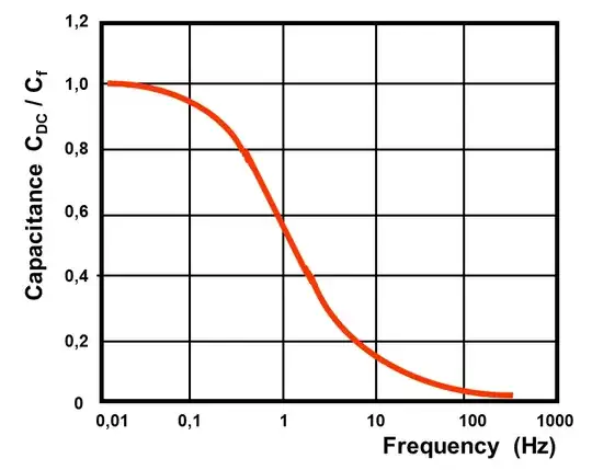
Cap-Frequency
^ this chart is kind of astonishing, in the sense that capacitance drops to 50% at 1 Hz frequency.

However, I'm thinking they may still be useful for 'regenerative' braking. e.g. we can combine that with say some low resistances say 1 ohm, this limits the currents and dissipate it as heat. Then with the huge capacitance, it works as some sort of 'RC filter'. e.g. for a motor spinning rather fast, we may not be able to stop it in 1 cycle, but that the combination may be able to stop it say in 10s of seconds and a fraction of that energy gets stored into the super capacitor. Hence, I'd guess we can re-use it, say when we want to spin up the motor again.

This is something that may be worth experimenting. This would likely work if say we can estimate the energy that need to be absorbed/dissipated and stored in the super capacitor. It is unlikely to stop a large motor or one that is spinning so fast that the energy cannot be fully adsorbed, but I'd guess it could be useful in situations. The attractive thing is partly the 'regenerative' aspects of this, and that actually the resistors would dissipate less heat as the super capacitor gets charged up (the energy is literally stored). We can have that 1 ohm in series with the capacitor and say a modest 10 ohm in parallel with the capacitor say to GND. This would help dissipate the rest as heat if the energy is not adsorbed, but we lose the 'regenerative' aspects of it. edit. Out of curiosity, I checked the specs of one super capacitor that is rather low cost:
https://www.digikey.com/en/products/detail/sruite-electronic-technology-us/SCE5R5H105/13901742
its spec is 5.5v 1F.
However, its internal resistance (ESR) is some 10 ohms or more! This means even if we'd just connect the capacitor alone, it won't absorb large currents, so the braking effect is at least limited and takes longer to stop a motor with a lot of momentum. There are also rather poor temperature limits 25-70 deg C. I'd guess they can be used in parallel, but it'd cost.

On a side note, if abrupt stopping is necessary, and for a motor or system with a lot of momentum, hence a lot of energy to remove. Unfortunately, I think only mechanical methods is possible with that, it would also generate a lot of heat, as mentioned could be pretty large amount of watts/heat in a short time. Electrical means could mean needing means to remove a large amount of heat in a short time.