Of the two circuits, would you prefer one over the other?
2 Answers
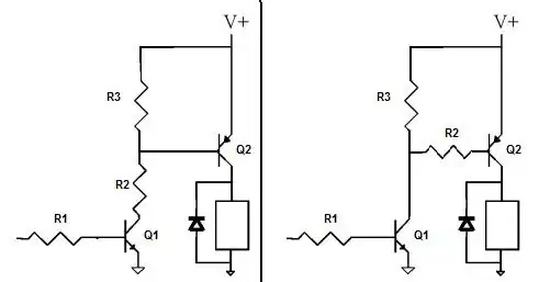
In most applications it doesn't matter. The first circuit will turn off the PNP a little faster, which would only matter in high speed switching, like if the load was being PWM controlled.
Here is yet another topology to consider:
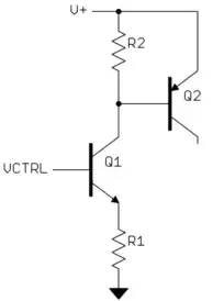
This only works if V+ is about a Volt or more higher than the highest VCTRL can be, but can be useful when that is true. I'll let you think about how it works.

- 310,974
- 36
- 428
- 915
-
2That's one of Olin's favorite circuits and is much more powerful and useful than is apparent at first glance. It is very slightly harder to design properly in some cases but is well worth understanding and filing away for future use. At another glance it may appear to be making a bad common mistake, but it isn't. Glance again :-). If this circuit seems straight forward and not really different from the other two, look again. – Russell McMahon Feb 09 '12 at 19:07
-
I also like a variation of the above where there's a resistor on the emitter of Q2 (in addition to the other two resistors shown). The output current will be proportional to the amount by which VCtrl exceeds some minimum voltage. – supercat Feb 09 '12 at 21:06
-
Hmmm ... the only thing I can think about is that R1 will limit the BE current of Q1, so no need to use a resistor on the base of Q1. – lyassa Feb 09 '12 at 22:37
-
1@lyassa: That is true, but also consider how the base current of Q2 is controlled. – Olin Lathrop Feb 09 '12 at 22:48
-
I was thinking about that, but I couldn't see difference in behavior than the circuit on the left. In your circuit, when Q1 is saturated, then R2 and R1 are voltage divider, just as is the case with the circuit on the left, R2 and R3 become voltage divider when Q1 is saturated. When Q1 is off, then the base of Q2 is at V+ in both circuits. Thanks for this challenge ... but now I am dying to know the answer :) – lyassa Feb 09 '12 at 23:00
-
1@lyassa: Q1 never saturates, and R1 and R2 don't form a voltage divider. Q1 acts as a controllable current sink. For a given VCTRL, the current Q1 sinks is pretty constant and independant of V+. You can arrange it to be what you need to turn on Q2 plus the current thru R2. – Olin Lathrop Feb 10 '12 at 00:00
-
1@OlinLathrop Got it. Thanks for this bit and the lots of other info you provide on this forum. – lyassa Feb 10 '12 at 00:11
-
@OlinLathrop Does this make it easy to use a DAC to control the current out of Q2? – Michael Pruitt Feb 11 '12 at 03:37
-
@Michael: Not in this configuration as is because the resulting current is proportional to the gain of Q2, which is rather unpredictable from part to part. – Olin Lathrop Feb 11 '12 at 16:33
-
I wish you've actually explained why the first circuit would "turn the PNP off a little faster". I've just built both and observed no measurable differnces, while my transistor seems to turn off after a considerable delay... – Bartek Banachewicz Mar 25 '21 at 21:57
Call the circuits A & B (for left & right).
As shown, both are equally good and both achieve much the same result.
In some cases if there was extra circuitry involved one or other may be better.
For example, if you wished to drive two PNP circuits from the same NPN circuit at the same time then circuit A allows slightly more design independence. For example, if one pnp was at V+ = 3V3 and the other was at V+ = 12V, then circuit A would still be easy to design properly, whereas using circuit B would leave uncertainties what happened to the collector of Q1 when Q1 was off.
[Decided to remove extra explanations].

- 147,325
- 18
- 210
- 386