12

I am designing and building circuits which use 100Mb/s on a Low Voltage Differential Signaling (LVDS) bus. Some of these signals need to travel between PCBs on hand made cables. The problem is that I have no way of verifying the quality of the cables and termination.

If I was a millionaire, I'd get an expensive 'scope or a vector network analyser. But failing that, is there some way I can measure the reflected signals, or the impedance of the cable?

(I have a 150MHz bandwidth, 500MSPS 'scope available).

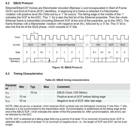
Added: Information about the data on the wire, taken from the ET1200 datasheet.

Ebus waveform

Added: 21 hours to go. Last chance for the bounty. Can anyone suggest even a quick and dirty way to measure impedance? Perhaps some kind of bridge where I could compare the cable against a known good cable?

Rocketmagnet
  • 26,933
  • 17
  • 92
  • 177
  • 1
    "100Mb" might be a spec for a memory, but not for a communications channel since the units are clearly wrong. What then do you really mean by "LVDS" (which of course should have been spelled out anyway)? Getting basic easy stuff like units wrong means we have to assume lots of other stuff is wrong and there is no way to know what you are actually asking. – Olin Lathrop Feb 09 '12 at 15:01
  • 1
    100 MB - with a capital B is the units for memory. Lowercase b means bits, so 100Mb means 100 megabits. Yes, it should include time so 100Mb/s is correct. LVDS stands for Low Voltage Differential Signaling. – MarkSchoonover Feb 09 '12 at 15:47
  • 3
    @Olin: Are you sure? Then what do people mean when they refer to 100Mb Ethernet? (Google it) Do they mean it can 'remember' 2^20 bits? No, people often use 100Mb as (very) short for 100 mega bits of data transferred per second. Agreed that the correct units are Mb/s. LVDS is always called LVDS. People practically never write it out in full: Low Voltage Differential Signalling. – Rocketmagnet Feb 09 '12 at 15:53
  • 12
    @OlinLathrop, Do we now have to spell out "Transistor-transistor logic" or "complimentary metal-oxide-semiconductor logic" every time we want to talk about TTL or CMOS? – The Photon Feb 09 '12 at 16:28
  • @Rocketmagnet - When people refer to "100Mb Ethernet" they are referring to it **wrong**. It's "100Mb/s Ethernet" (or "100Mbps Ethernet"). The fact that a lot of people **incorrectly** call it that does not make it correct (it just makes the people who call it that look silly). Is not typing the additional `/s` or `ps` that much of an affront? – Connor Wolf Apr 08 '12 at 06:30
  • @OlinLathrop - LVDS is a very common signaling scheme in high-speed logic (it's similar to things like ECL in commonality). It's common enough that he shouldn't have to define it. – Connor Wolf Apr 08 '12 at 06:32
  • @Fake Name. If I'd known it would have caused such a fuss, I would have put in the /s. I wasn't expecting such aggressive pedantry. – Rocketmagnet Apr 08 '12 at 10:09
  • @Rocketmagnet - Frankly, I wouldn't have noticed if it was just in the original question (I would have assumed it was a typo). However, you seemed to be defending the position in your comment, which was what I was really reacting to. Incidentally, we have a number of pedants here. Engineering requires very precise terminology. – Connor Wolf Apr 08 '12 at 10:18
  • @Fake Name: Pedantry is fine and expected. Olin's aggression is not. – Rocketmagnet Apr 08 '12 at 11:52
  • @Rocket: Sloppiness with units is never acceptable in engineering, and must be stomped on hard whenever it occurs. – Olin Lathrop Apr 08 '12 at 14:42

3 Answers3

5

You don't have to spend a million dollars do get a decent VNA. Since you have the skills to build circuits, you can build one yourself for about $400 USD. I've been building up a N2PK VNA over the past several months. You don't need any special tools, just a steady hand, and a good soldering station. There's an active Yahoo Group, in the files section there are plenty of completed projects. I've sourced most of the parts through Digikey, with a few from Mouser, and MiniCircuits. I've been writing up my progress on my website too.

MarkSchoonover
  • 1,113
  • 10
  • 17
3

Here's the cheapest I can come up with.

Directional coupler diagram

First, you need an rf synthesizer. If you don't have that, get your digital signal to output a pure square wave (either use the clock signal or send 1010... from your data line), and then use a lowpass or bandpass filter to transform that into a pure-ish sine wave.

Between the source and your circuit under test, connect a directional coupler, in the direction so that the coupled output is getting the reflected signal, not the source signal.

Now connect an rf power detector to the directional coupler's coupled port. Now you can use a multimeter to measure the power in the reflected signal.

If you use Minicircuits, you can get the directional coupler and power detector for something like $150, or you can probably find these parts for even less on EBay.

There will be all kinds of errors in this approach, because you don't have the equipment to calibrate it. The directivity of the directional coupler will limit the minimum reflection coefficient you can measure. But if you adjust your termination to minimize the voltage at the power detector output, you're probably close to optimizing the match.

Edit

Should add, since you're talking about LVDS, you're presumably talking about a differential line and a differential termination. Which means for this scheme you'll need a balun between the test instrument and your DUT. Which is yet another potential source of errors.

The Photon
  • 126,425
  • 3
  • 159
  • 304
  • Thanks Photon. This is more like what I'm after. Since this is LVDS, do I need a pair of directional couplers? Why use a pure sin wave? Why not use my real signals? Surely this would make it a more accurate test. – Rocketmagnet Apr 07 '12 at 21:18
  • Maybe I could calibrate it. I can create a situation with maximum reflection by leaving out the terminator. And I can create minimum reflection using a 100R HDMI cable and 100R terminator. – Rocketmagnet Apr 07 '12 at 21:24
  • The directional coupler and rf detector won't have particularly uniform response over frequency. So you won't really know what's the response to your square-ish wave input. Also, you won't know the phase response at each frequency, so overall its a pretty limited measurement. But it could get you pretty close to a good match. – The Photon Apr 07 '12 at 21:25
  • Cool. I'm reading up on directional couplers now. Is there such a thing as a differential directional coupler ? – Rocketmagnet Apr 07 '12 at 21:39
  • @Rocketmagnet - Don't ground the coupler? Or use a [balun](http://en.wikipedia.org/wiki/Balun) to go from single-ended to differential. – Connor Wolf Apr 08 '12 at 06:28
  • I really enjoy this solution. I love engineers whom know how to goof around with tricks like this, there is nothing more fun then "cheating" the standard way. With some work we could fab everything! A PCB directional coupler with a small operating range is pretty easy to damage fab and a 1GHz oscillator would be pretty easy, as far as these things go, to make ourselves, now there is a fun project! – Kortuk Jun 22 '12 at 02:02
1

In my opinion, the most obvious thing to do is to build an oscillator (or a multivibrator, to have square waves) with variable frequency and look at the signal at the other end of the cable if the degradation is acceptable.

But first you should define some dimensions: 100 Mb/s it's the overall bandwidth or only for the payload? You should first convert it into a signal frequency (in Hz), and then check the length of the cable to make sure that it's of the proper length.

I think that measures make sense when you have an hypothesis to check, otherwise you won't know what to do of the results.

clabacchio
  • 13,481
  • 4
  • 40
  • 80
  • Problem is that my oscilloscope isn't fast enough to do any meaningful measurement at this speed. A scope like that costs thousands of pounds. – Rocketmagnet Apr 01 '12 at 14:21
  • @Rocketmagnet you can still make sure that a 100 MHz sinewave is passed, and that the line is of the proper length to have stationary waves – clabacchio Apr 01 '12 at 14:38
  • Well, the cable is pretty short (about 300mm) compared to the wavelength. I'm not sure exactly what the wavelength would be, because apparently the propagation velocity depends hugely on the medium. – Rocketmagnet Apr 01 '12 at 14:40
  • One thing I was considering was to put an LVDS transmitter going at 100MHz at one end of the cable, and measure the amplitude of the voltage across the termination resistor using a high speed opamp configured for peak detection. That way I can at least compare cables to see how much power is dissipated across the terminator. Does that sound sensible. – Rocketmagnet Apr 01 '12 at 14:43
  • @Rocketmagnet, That's essentially putting an RF detector at the termination end. But what does it tell you? If you have too-high termination resistance you'll measure a higher peak voltage. If you have too low, you'll measure a lower peak voltage. But how will you know when you're perfectly matched? How will you know if you're overshooting or undershooting? – The Photon Apr 01 '12 at 16:24
  • 1
    Also, critical line length depends more on the rise & fall times of your source signal than on the bit rate. So what are your rise & fall times? Problem is, you don't have the budget for the test equipment that could tell you...I thin the reason you haven't gotten many answer to your question is, there's no magic bullet. If you want to work at 100 MHz and up, you need to budget for proper test equipment at those frequencies. – The Photon Apr 01 '12 at 16:27
  • What I thought was that, if the termination and cable matched, then all of the energy would be absorbed by the terminator, and none would be reflected. Therefore, the greater the voltage, the better the match? Surely it can't be as simple as higher resistance = higher voltage? – Rocketmagnet Apr 01 '12 at 17:00
  • @Rocketmagnet no, because the bigger the termination, the smaller the current; the match is when the resistances are equal – clabacchio Apr 01 '12 at 17:08
  • Yes, but I can easily get the resistor correct. An Ohmmeter is very cheap. What happens to the voltage across the terminator if I vary the impedance of the cable? – Rocketmagnet Apr 01 '12 at 17:11
  • 1
    If the termination R is greater than the line impedance Z0, you get a reflection with positive voltage; so if you measure voltage at the termination, it is higher. If R < Z0, you get a reflection with negative voltage, so you measure a lower voltage at the termination. But if you are doing this by varying Z0 instead of R, you also create at mismatch at the source end, and you get multiple reflections in the line. What is the end result measured in terms of peak voltage at the termination end is not trivial to predict. – The Photon Apr 01 '12 at 17:24
  • One thing you could do is get a vector voltmeter and measure the VSWR on the line. EBay prices are in the order of $1000-$2000, which I think is only about 35p in British money. But this is very tedious and you are well on your way to Mark's answer and building your own VNA. – The Photon Apr 01 '12 at 17:28
  • I wish this wasn't so difficult. Anyone up for starting a collaborative open sourced 1Gs/s scope project? – Rocketmagnet Apr 01 '12 at 18:20