0

I have an application where I want a microcontroller to be able to sample the AC line voltage (scaled down through a voltage divider). The AC power comes into the system, and then an off-the-shelf board-mounted isolating converter is used to generate my DC system voltage. I'm questioning my proposed implementation because it seems that if the DC domain is isolated, it could theoretically be at any potential above or below (within reason) any of the three AC lines.

schematic

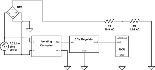
simulate this circuit – Schematic created using CircuitLab

My analysis says that yes, I do need to connect AC ground and/or neutral to my DC ground. In my actual design I have added clamping diodes near R1 and R2, but I left them out here for simplicity.

Am I correct in that I need to connect the AC Ground or Neutral to the DC ground?

Brendan Simpson
  • 2,154
  • 12
  • 20
  • 1
    Only if you want to blow up your bridge rectifier. You've already grounded the (-) pin there so your AC and DC domains are connected. – brhans Oct 10 '16 at 18:21
  • your gnd symbol on diode bridge is 1 diode drop from line or neutral depending on connection. Neutral is gnd'd at the transformer. A differential amp is better witha voltage divider and suitable CM range. – Tony Stewart EE75 Oct 10 '16 at 18:21
  • Consider an optocoupler. How much accuracy do you need? – CL. Oct 10 '16 at 18:23
  • @CL. I hadn't considered an optocoupler. That is a good idea, and might work out better for me overall. I get to retain the isolation and most of the accuracy. I am using the sampled AC for some phase angle control. – Brendan Simpson Oct 10 '16 at 18:25
  • To understand the problem with rectifying mains and providing a GND reference see https://electronics.stackexchange.com/questions/259908/help-learning-from-a-mistake-connecting-an-oscilloscope/259918#259918. – Transistor Oct 10 '16 at 18:33

0 Answers0