I have this working
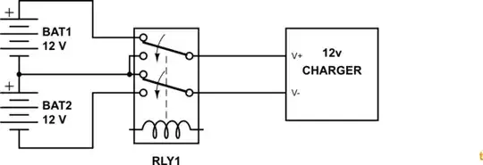
simulate this circuit – Schematic created using CircuitLab
An Arduino commute both relays and a power adapter charge each battery at a time.
I would like to replace each relay by a MOSFET. How can I do that?
I think the solution bellow will not work because DRAIN is always connected to SOURCE and this will short circuit batteries. MOSFETS only isolate from SOURCE to DRAIN.
When the D9 is HIGH, D10 will be LOW so the power adapter will never be charging both batteries simultaneously.
Sorry for the messy schematic.
Thank you very much.