0

I'm using a Raspberry to control a tubular motor for a window blind and I have an issue whent testing it, the relays used to operate the motor got "stuck" and stopped working after a few direction changes.

The motor has 4 cables. 1 neutral, 1 ground, 2 for each direcction. And work with 220V AC power.

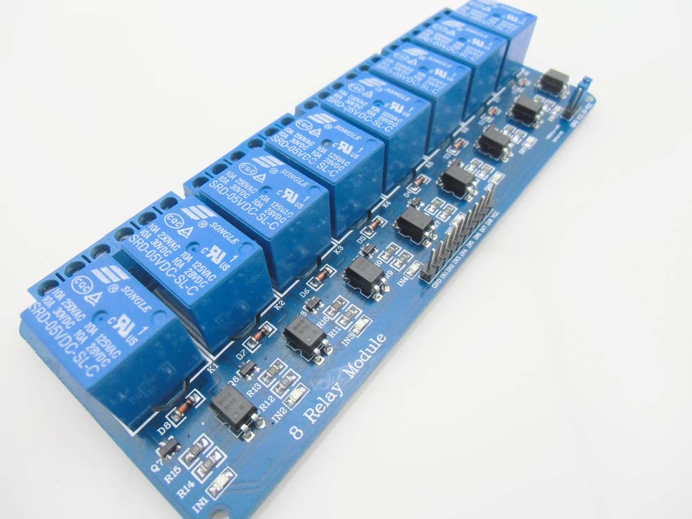
I use a relay board to control the current flow to each direction.

Here is a picture of the relay board: https://www.openhacks.com/uploadsproductos/are00108sl_1.jpg I cound't find the direct specs of it but the relay used is: SRD-05VDC-SL-C https://www.ghielectronics.com/downloads/man/20084141716341001RelayX1.pdf

Here is the motor specs: alsidoor.com/pdf/NICE/Nice-ERA-M-adapatadores-persiana.pdf Model E M 3017

So I use 2 relays to control both directions of the motor. And I made a software to activate one relay, and deactivate the other so I will change direction. And it works.. but after a few changes one of the relay got stuck and didn't work anymore. I tried with another and the same happend after a while.

In the specs it says that the relay can handle up to 10A of current.. and the motor only uses 1.1 A.. so it shouldn't have any problem to handle it.

What I think it's happening is that when the change is made, the tubular motor has some inertia and consumes a boost of power to change the direction and there is where it get stuck.

My question is.. is there any way to avoid this when changing the direction? I can make a pause between each change.. but eventually for any problem it may harm the relay anyway, so I would like a more elegant solution.

I don't really have an electronic background.. I'm a software developer so I don't know much about the specs of the pieces, I just connect the cables, but tha's why I'm asking if putting some resistence or change the relays I can fix this issue.

Any ideas?

Thanks.

Yind
  • 123
  • 7
  • If you look to the right of the page, you will see a column of **Related** questions. One has 4 votes [How to avoid damaging relay used for controlling motors?](http://electronics.stackexchange.com/questions/227217/how-to-avoid-damaging-relay-used-for-controlling-motors?rq=1). I think that answers your question , ie. your question appears to be a duplicate. I also found 10 votes [How to design ... for a solenoid relay driving an inductive load?](http://electronics.stackexchange.com/questions/42131/how-to-design-an-rc-snubber-for-a-solenoid-relay-driving-an-inductive-load) – gbulmer Oct 04 '16 at 18:19
  • You *might* get more help, and maybe avoid being closed as a duplicate, if you post links to the motor and relays. – gbulmer Oct 04 '16 at 18:23
  • Hint: soft-start. – Jakub Rakus Oct 04 '16 at 18:43
  • @gbulmer Those examples are not the same as my case, I don't invert the direction changing polarity, I do it opening the current in one cable of the motor or the other. I don't really have a strong electronic knowledge so those replies doesn't really help me. I would like to know what relay should I use, if I can adapt it to my relay board, if there another thing I can put between the motor and the relay to avoid the relay to stop working. Thanks. – Yind Oct 04 '16 at 19:56

1 Answers1

2

The Songle SRD-05VDC-SL-C data sheet found here lists the form C inductive load rating as 3A 120VAC. No inductive load rating is given for 240VAC and no mention is made of motor duty. Relays used for motor control must be capable of switching the motor starting or locked-rotor current which can be much higher than the normal running current. Because of that, relays that are designed to control motors usually have a motor power rating.

Applying a derating factor to the relay's resistive current rating is not the best way to select a relay for controlling a motor. The inductive rating that you have in this case does not necessarily apply to motor control use. If you are using the relay at 120 volts, it might be ok, but if you have tried it and are having problems, that probably proves it is not ok. If your voltage is 240 volts, it would not be at all surprising that the relay is failing.

I'm asking if putting some resistence or change the relays I can fix this issue.

Adding resistance will not help. You need to find relays that are rated for a 240 volt, 250W motor or have an inductive load contact rating that is at least several amps at 240 volts.

What you probably need is Songle SLA-05VDC-SC-A (Data Sheet) Note that this has one normally-open contact. That is all you need if you just need to connect one lead for one direction and the other load for the opposite direction. It is available mounted on a board with a driver circuit for example, here. Also note that the 120 volt HP rating is listed as 0.25 HP on the data sheet but 1 HP on the relay case. I think the data sheet is correct. Note that the motor that you have requires 250 watts input, so the output is probably not much more than half of that (1/6 HP).

  • thank you so much!, that's what I wanted to know. I just have one more question. Can I change the relays directly on my relay board? or it won't work that way? because I need to control 4 motors at the same time, so I need 8 relays. And couldn't find a relay board with that specific relay. – Yind Oct 05 '16 at 12:23
  • The driver circuits on the relay board can likely drive that relay, but it is larger and the pin placement is likely different. Compare the two data sheets to determine the exact differences. The original relay came close to working. How much delay did you use between turning one off and the other on? I think something like 20 to 60 ms would be good. The life of the relay would still be considerably shorter than normal, but it might be ok for your requirements. –  Oct 05 '16 at 13:22
  • I also saw a board with 4 relays that looked like a little better relay. I couldn't find a motor rating. –  Oct 05 '16 at 13:41
  • Thank you so much for the advice. I'm going to use this: http://robotdyn.com/catalog/relays_switches/relay_module_2_relay_5v_30a/ And it will allow me to do exactly what I was trying to do. Thanks. – Yind Jan 12 '17 at 14:43