1

Below is an illustration about heterodyne principle:

enter image description here

I can see the motivation behind heterodyning. I read that it is basically done to obtain a "fixed" frequency for the amplifiers at different incoming tuned RF carriers. But look at for instance the above illustration. The mixer produces a beat freq. which is |f2-f1|. But how can that be fixed for different carrier frequencies? I mean if oscillator has a fixed freq. f2, how can f2-f1 be fixed when f1 changes?

I really couldn't find an answer by googling this. Am I missing a point here?

Bimpelrekkie
  • 80,139
  • 2
  • 93
  • 183
user16307
  • 11,802
  • 51
  • 173
  • 312
  • Because you choose the LO frequency to keep it constant. Initial "alignment" of a traditional AM radio spends quite a lot of effort to keep the LO and RF sections in track across the whole AM band. LO is tuned by a separate capacitor on the same shaft... See https://en.wikipedia.org/wiki/Variable_capacitor –  Oct 04 '16 at 12:40
  • same question to you as well: but the am radios i used are tuned by only 1 knob which I was thinking a variable cap. Isnt that true? are u saying we need two knobs one for f1 and one for f2 here? – user16307 Oct 04 '16 at 12:42
  • i thougt the cap is for to adjust the resonant freq. of the lc tuner to pickup right rf waves – user16307 Oct 04 '16 at 12:43
  • One is - the other one is used to adjust a second LC resonant circuit, which is part of the local oscillator. See the first image on the Wikipedia page. –  Oct 04 '16 at 12:44
  • but i can only see one tuning knob here:https://img0.etsystatic.com/000/0/5634215/il_fullxfull.168337758.jpg other one is for volume. whats wrong? – user16307 Oct 04 '16 at 12:47
  • Nothing is wrong. That knob drives two separate variable capacitors, that's all. Or sometimes 3 in better radios (with double-tuned RF stages). –  Oct 04 '16 at 12:53
  • the capacitors causes the same frequency change both in f1 and f2 right? – user16307 Oct 04 '16 at 12:57
  • Back to my first comment : yes, but only if you take the trouble to align the tuned circuits properly. There is a procedure to be followed (at the factory, or afer a repair) with every AM radio to do this. http://www.vintage-radio.com/repair-restore-information/valve_alignment.html - the "AM RF alignment" section. –  Oct 04 '16 at 13:05
  • the secret to "googling" is keywords like theory, heterodyne, IF RF filter – Tony Stewart EE75 Oct 04 '16 at 13:35

4 Answers4

4

The point is that if you want to tune to a new frequency (radio channel) then you move the local oscillator frequency to keep the intermediate frequency precisely the same as it was. Then and only then will the IF filters amplify the new channel and largely reject close by channels.

So if your IF is 455 kHz and your LO is 1500 kHz then this tunes in a radio station having a frequency of 1045 kHz. If you want to tune in a radio station at 1000 kHz, the LO needs to drop to 1455 kHz to maintain the IF at 455 kHz.

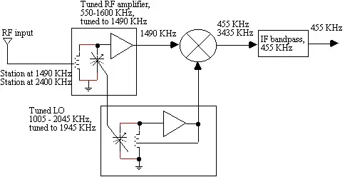
To help the OP understand this a bit more here's a block diagram of ganged capacitor tuning to operate the antenna filter and local oscillator together: -

enter image description here

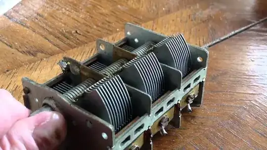
Sometimes three ganged variable capacitor are used: -

enter image description here

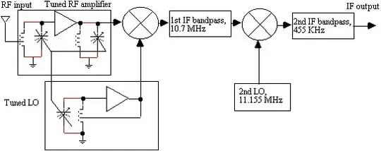
Sometimes dual IFs are used for extra image rejection: -

enter image description here

Pictures courtesy of this site

Triple ganged tuning capacitor for AM broadcast bands: -

enter image description here

And one last attempt to make this clear: -

enter image description here

The top picture shows a typical AM spectrum with several channels occupying the range 530 kHz to 1600 kHz. The middle picture has all those channels (mainly in red) reversed and shifted down because of the mixer and LO (1355 kHz). Note the position of the 1600 kHz channel (green) has reversed through 0 Hz and so I've shown it dotted along with the other channels that mirror then reverse through 0 Hz.

Note the desired channel (in gold) at 900 kHz has effectively moved down to 455 kHz (1355 kHz - 900 kHz). In the final picture the I.F. filters get rid of all the channels apart from the gold one.

Andy aka
  • 434,556
  • 28
  • 351
  • 777
  • But what is causing what here? Here is the order?: Lets say I tune the AM station by adjusting the variable cap of LC circuit. f1 then changes because of me changing the cap. But how can LO know this change and adjust itself to keep f2-f1 a constant freq.? What tells LO to do this? – user16307 Oct 04 '16 at 12:29
  • All channels are simultaneously heterodyned but only one channel heterodynes to the right IF. The LO is just a means to an end and certainly, if not manually set correctly either no station or the wrong station will be selected. – Andy aka Oct 04 '16 at 12:31
  • I dont get this part. You mean LO is also manually adjusted? – user16307 Oct 04 '16 at 12:35
  • Every broadcast radio I've seen requires the LO to be manually tuned to select the station you want. The LO has to be the IF away from the channel you desire to listen to. – Andy aka Oct 04 '16 at 12:37
  • pardon my ignorance. but the am radios i used are tuned by only 1 knob which I was thinking a variable cap. Isnt that true? are u saying we need two knobs one for f1 and one for f2 here? – user16307 Oct 04 '16 at 12:40
  • Most radios simultaneously tune an antenna filter AND the LO - it's a tandem operation BUT I've seen designs where the input filtering was fixed and broadband and the knob only adjusted the LO. – Andy aka Oct 04 '16 at 12:50
  • 1
    During tuning to the AM station the LO also moves in the correct direction. this is because in the design of the radio the tuning capacitor and the LO capacitor are both placed on the same shaft. Ofcourse some trimming is done to keep this working correctly – Decapod Oct 04 '16 at 12:52
  • oh so you are saying when I turn the knob the cap varies and lets say increases f1 and this variation in capacitor causes the same freq. increase in LO? so f1 becomes f1+deltaf and f2 becomes f2+deltaf and the difference remains the same? is that what happens? – user16307 Oct 04 '16 at 12:54
  • See the adds in my answer and yes, the difference remains the same. – Andy aka Oct 04 '16 at 12:58
  • That is indeed what is happend. If however you have a broadband input then you change only the LO to get the new receiving frequency. Then no tuning is done on the antenna filter. See the improved answer of Andy – Decapod Oct 04 '16 at 12:59
  • @Decapod thanks for contributing - I did mention the broadband option higher up this list of comments. – Andy aka Oct 04 '16 at 13:02
  • @Decapod AM is not considered as broadband input right? Is there analog radio transmission which uses broadband? – user16307 Oct 04 '16 at 13:07
  • @user16307 Certainly AM can be considered a broadband range of frequencies and with special care the input variable tuning stages may be omitted leaving just a general broadband filter that is fixed in tuning. Don't confuse the term "broadband" with meaning something to do with the internet! – Andy aka Oct 04 '16 at 13:22
1

Yes, you are missing something.

F2 is varied, to choose different input frequencies, but fixed, once an input frequency has been chosen.

At least, that's what happens at the first mixer. For second and subsequent mixers, the input frequency is the previous IF, which is fixed, so the local oscillator can be fixed as well.

Neil_UK
  • 158,152
  • 3
  • 173
  • 387
0

The task of the mixer is to linearly translate all the RF signal frequencies to a different frequency region (intermediate frequency). The frequency difference is set by the frequency of the local oscillator.
A intermediate frequency amplifier usually employs a frequency-selective filter designed to separate the desired signal from all the others presented to it by the mixer. This filter is not made to be frequency-agile. It may be made up of fixed-frequency crystals, or inductor-capacitor resonators that can be tuned over an extremely narrow range. Such filters are often mulit-stage so that they can attenuate unwanted noise and undesired signals effectively. Filter tuning, (if allowed) is only meant to adjust its passband shape, not so much to adjust its centre frequency. So we generally assume that the intermediate-frequency stage in a receiver is at a single, fixed frequency.
The local oscillator, on the other hand, is often designed to be frequency-agile. The frequency of this oscillator is very easily set by a single resonator, often an inductor-capacitor pair. Either inductor or capacitor is variable, allowing frequency to be varied over a wide range.
Thus, a superheterodyne receiver can be tuned over a wide range with a variable-frequency oscillator, yet be very selective in picking out one desired signal out of many others with a fixed-frequency intermediate-frequency amplifier.

glen_geek
  • 23,591
  • 1
  • 22
  • 50
  • I think my question was not asking why it was supposed to ask how instead. i know the reasons behind it. I just was wondering how f2 follows the increase in f1. – user16307 Oct 04 '16 at 13:15
  • f1=f2+fbeat. or also possible: f1=f2-fbeat. f2 is set by the radio operator. fbeat is at a single, fixed frequency. The "how" is buried in the mixer...in some respects it is a very non-linear element to achieve sum&difference. Even so, the frequency-selective I.F. amplifier is able to linearly select-out the desired signal. – glen_geek Oct 04 '16 at 14:40
0

Note that you can actually do away with the RF tuning and just tune F2, with the RF selectivity being a simple bandpass covering the whole band. Providing the mixer is sufficiently good (Can handle the relatively large input power from the sum of all the stations without IMD3 becoming a problem) and providing the IF is chosen so that the image falls outside the bandpass this can work quite well (This usually argues for a high IF or dual conversion set).

The old sets usually had a multi gang variable cap with two of three sections on a single shaft such that the RF tuning and LO could be arranged to track, but that is a pain in the arse in many ways, especially if typing to build a general coverage set.

Note that the whole reason we do all this is so that most of the selectivity can be at a single fixed frequency to allow the use of crystal filters, ceramic resonators or SAW filters (None of which are tunable) which have far better selectivity then a variable filter based on a couple of LC tanks.

Modern design for the HF bands usually does the input bandpass thing followed directly by the mixer with no RF tuning as such, but modern switching mixers have amazing IMD dynamic range, doing this with a low level diode ring is at best a compromise.

Dan Mills
  • 17,266
  • 1
  • 20
  • 38
  • I think my question was not asking why it was supposed to ask how instead. i know the reasons behind it. I just was wondering how f2 follows the increase in f1. – user16307 Oct 04 '16 at 13:16
  • If you change F2 then the frequencys that will give an output at the IF change by definition (That is rather the point). As I say, modern general coverage sets avoid variable tuning circuits in the F1 path in front of the mixer. If I have a 455KHz IF and want to tune a station at 1MHz, with a high side LO, the LO MUST be 1.455MHz, if I want to tune a station at 1.1MHz, the LO must be 1.555MHz, both stations could be present at the mixer input (And actually in the output spectrum), but only the one where the difference is correct will pass the IF filters. – Dan Mills Oct 04 '16 at 13:33