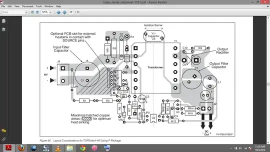
This picture is from top252 ic of smps. Out of million questions, why is a capacitor[C6] is connected across transformer.
-
2Hmm, we usually expect a schematic instead of a PCB layout. Luckily for you C6 is a Y1 Capacitor across an isolation barrier. Many questions have been asked about Y class capacitors in switched mode mains supplies, like in this question: http://electronics.stackexchange.com/questions/216959/what-does-the-y-capacitor-in-a-smps-do and here's another one http://electronics.stackexchange.com/questions/220606/purpose-of-capacitor-across-transformer-in-ac-dc-power-supply?noredirect=1&lq=1 – Bimpelrekkie Oct 04 '16 at 09:12
-
These links are really helpful. I have a follow up questions in the 1st link's answer. In 5th para it is written *'we have no choice but to connect these capacitors to the input "live" and/or neutral'*. Doesn't this couple the said high frequency noise to the main lines. – Raj Kiran Nov 01 '16 at 13:25
-
*Doesn't this couple the said high frequency noise to the main lines* No because currents travel in loops, this is also true for noise etc. The loop is mains-ground - switching transistor - transformer - Y1 capacitor - mains ground. There is no reason for the noise to go into the mains, back through the mains wire, power socket etc, as there is no return path for that loop. – Bimpelrekkie Nov 01 '16 at 15:55
-
In 5th para it is written that class 2 type is an unearthed one. so there is no ground to link up this noise. It has to pass through neutral or live wire. – Raj Kiran Nov 02 '16 at 14:00
-
*It has to pass through neutral or live wire* but it will not because there is no **loop**. So most of the RF noise will just loop inside the supply and not go out via mains. Mains is a high impedance for RF signals so it is difficult for RF signals to enter the mains. – Bimpelrekkie Nov 02 '16 at 15:00
2 Answers
Yes, it's not all that clear but basically it's about reduction of EMI generated by the secondary winding.
Normally, for a 3-pin AC or DC input, this capacitor would connect from the secondary to the earth pin.
The secondary is of course floating but, due to the construction of the transformer, capacitively connects to the primary winding. That primary winding has a clean side (the DC rail) and a dirty side (the side that is switched on and off by the MOSFET in U1). So there is a large, AC, high frequency voltage capacitively coupled to the secondary that raises and lowers the whole of the secondary circuit at high speed.
This will generate EMI on the output wires and the device would fail emission testing. The added capacitor seeks to significantly reduce this effect by shunting this capacitively coupled voltage back to a fairly clean point in the circuit. There is no earth point so the positive supply voltage is used but equally, the negative supply voltage line would also work.
- 434,556
- 28
- 351
- 777
-
can you provide some mathematics/calculation for the capacitor value. As per the datasheet the switching frequency is 132kHz. – Raj Kiran Nov 01 '16 at 13:41
-
@RajKiran - it's job dependent and the make-up of windings in the transformer dictate what it should be. At the other end of the scale there is emission testing and rules change from one decade to the next so that also affects how large a value is needed. There is no clear-cut theory. – Andy aka Nov 01 '16 at 14:13
In short C6 provides a return path for the high frequency signals that are generated by the switching on the primary side of the transformer. Part of these signals are coupled through the transformer to the secondary (low voltage) side of the transformer.
We all know currents travel in loops and without C6 there is no way that these signals can travel back to the primary side of the transformer. That would result in the signals having no choice but to travel through the output of the supply and causing EMI problems.
C6 provides a path for these signals to travel back to the primary side of the transformer. This keeps the loop short and prevents EMI emissions.
C6 has to by a Y-class capacitor for safety reasons. It needs to be able to withstand high voltages and also if it fails it is not allowed to fail and make a short as this will put mains voltage at the output of the supply !
- 80,139
- 2
- 93
- 183
-
-
No, there is no formula. In practice values between 1 nF and 10 nF are used. A value of 10 nA might give you more of a "tingle" when you touch the secondary side. – Bimpelrekkie Nov 02 '16 at 14:57
-
thanks, i guess i will come with more doubts. But for now that's it. – Raj Kiran Nov 02 '16 at 16:10
