0

Possible Duplicate:
Adding voltage cutoff to a circuit?

Adding voltage cutoff to a circuit?

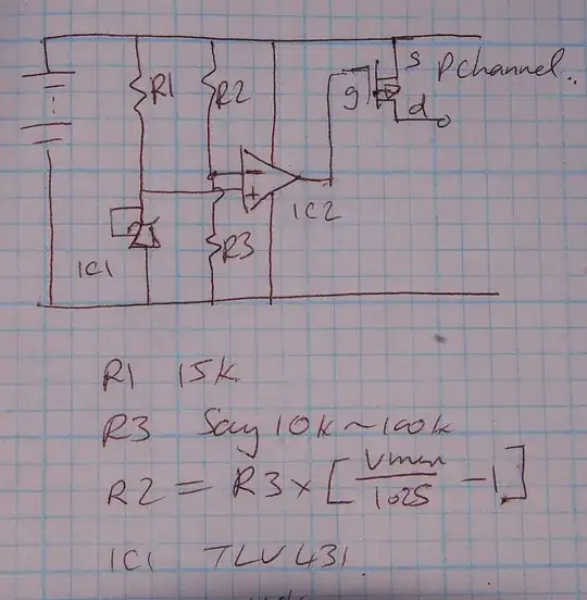
I'm powering a project with a 3-cell 11.1V LiPo battery. What circuit do I add to make the unit stop drawing power when the voltage from the battery drops below 9V? The goal is to protect the LiPo battery from discharging below 3V/cell. my battery is: http://www.hobbyking.com/hobbyking/store/uh_viewItem.asp?idproduct=6501 by the way, i looking do draw max if 2 ampere from it, hope it wont change nothing...

Niv Minkov
  • 1
  • 1
  • 1

2 Answers2

0

See my prior answer here which provides several circuits.

P-Channel MOSFET

Russell McMahon
  • 147,325
  • 18
  • 210
  • 386
-1

What I would do is place a series resistance (R1) and 9V breakdown zener diode in parallel with the battery (with R1 attached to the positive terminal of the battery). Place a resistance (R2) from between R1 and the 9V diode to the base of an NPN BJT and another (R3) from the base of the BJT to the negative terminal of the battery. Place the load between the BJT's collector and the positive terminal of the battery.

When the BJT's BE voltage drops below 0.7V (or some other value depending on the device), the CE junction will stop conducting (and so no current will be drawn from the battery).

When the battery's voltage is high, the voltage across the diode will be 9V. When the battery's voltage drops below 9V, so will the diode's. This will decrease the voltage across the BE junction. The values of R2 and R3 should be such that the voltage across R3 equals 0.7V when the voltage across the zener diode is 9V (and therefore less when the zener voltage drops).

Hope this helps.

JonaGik
  • 251
  • 1
  • 3
  • 6
  • You should post a schematic to explain your idea, but from what I could understand, it's not going to work. -1 since when you will add some schemes and clarifications. Where is connected the emitter? How can the battery supply the current through the base? – clabacchio Feb 03 '12 at 11:38
  • @clabacchio I'm not sure how I would go about posting a schematic. The battery can supply current through the base via R1 and R2. The emitter is earthed. Basically the idea is that the zener diode is at a voltage of 9v when the battery is above 9v or less when the battery is less. A voltage divider across the zener diode produces a voltage of 0.7V when the zener is 9V or less otherwise. When it is less, the BJT stops conducting, hence stopping drain of the battery. – JonaGik Feb 04 '12 at 03:01
  • I understood somehow just because I've seen Russell's schematic, which anyway is more efficient because it's not effective turning on and off a transistor with a simple voltage divider when the input is slowly changing like a battery. COULD make sense but in my opinion is not the best solution – clabacchio Feb 04 '12 at 09:04