1

I would like to control the strength of 4 electromagnets using a PWM output from an Arduino. I got the Arduino program working, but now I have to do the hardware.

  • I got four magnets which draw up to 9A @ 24V
  • I got two 24V power supplies which can deliver up to 20A each (so I need two for 4 magnets)

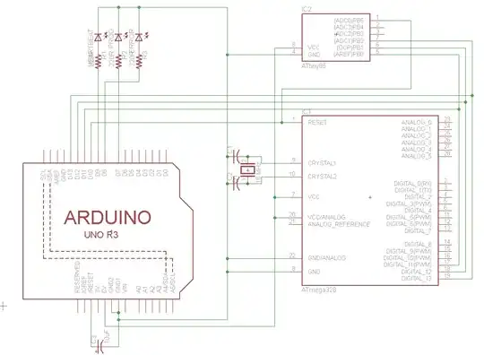
I drew up this circuit below to control al four magnets using one PWM output pin. Will this work ?

And also: Do i need heatsinks on the mosfets ?

Thanks !

Circuit

MrExplore
  • 11
  • 1
  • 2
  • You may want to check out [these guidelines](http://electronics.stackexchange.com/questions/28251/rules-and-guidelines-for-drawing-good-schematics). I can see you put an effort in your schematic, but it looks quite extravagant. – Dmitry Grigoryev Sep 30 '16 at 12:56
  • What frequency PWM? Even if Vdrive is OK (see other answers) the drive current to the gates needs to be high enough at the switching edges to give fast enough switching. At low PWM frequencies low I drive is OK but at say 10 kHz up you want say <10 Ohms from driver to gate and drive current PEAK capability of 100's of mA. – Russell McMahon Sep 30 '16 at 15:29
  • Dmitry: I'll look into that - I'm not an expert in electronics ans lack the software, but I try to present it as clear as possible Russel: pff, I'd have to look into that, what frequency would be advisable ? I think on Arduino the frequency can be set – MrExplore Sep 30 '16 at 21:39

2 Answers2

1

BUZ11, and indeed most FETs, need rather more than 5v on the gate to turn on properly, you really need at least 10v. You can get so called 'logic level' FETs, which are specified to turn on fully with a 5v gate drive.

If you were just going to switch them on and off, then the 5.7k resistor (from a 10v source) would cut it, FETs don't draw any gate current when switched on. However, to switch them on and off requires a large amount of current to do it quickly, there is a large effective gate capacitance. All the time the FETs are switching on or off, they are dissipating a large amount of power. Switch slowly, frequently, or both, and you will put a lot of extra power into the packages. You really need a 'gate driver' therefore, capable of putting out around one amp per FET. With very slow PWM you may get away with less.

If you use a logic level FET, it may be sufficient to replace the 5.7k resistor with 10 ohms, and use one output per FET, so you get rather more current drive into the gates. This may be OK with a low PWM frequency, but you will have to check. I'm not sure why there's such a large resistor in the circuit, perhaps it's a hang-over from using the Arduino to drive bipolar transistors, where a current limiting resistor is necessary. When driving FETs, the problem is getting sufficient transient current to switch fast.

To put some numbers on the switching time, the IRL540 (linked in the comments) has a gate charge of 50nC at 20v. With 5.7k limiting the current to less than 0.5mA, it will take 100uS to shift the charge in and out. That means if the PWM frequency is 5kHz, the FET will never turn fully off or on, and will spend all its time dissipating some significant portion of 9A*24v. If you use one I/O per FET, with zero or near zero series resistance, then even if the current is only 20mA during switching, you will make the transition in a 2.5uS, and the FET will spend most of its time off, or on.

At 9A, the 40mohm of the BUZ11 will dissipate over 3 watts. That's too much for a bare TO220 package, you will need a heatsink. And that's before you start adding in any extra switching power dissipation.
Neil_UK
  • 158,152
  • 3
  • 173
  • 387
  • Thank you both for your answers. So what you're basically saying is that this is not going to work :) I wil look into logic level mosfets then. – MrExplore Sep 30 '16 at 21:10
  • In the following blog an IRL540 seems to be the way to go then ? (https://arduinodiy.wordpress.com/2012/05/02/using-mosfets-with-ttl-levels/) – MrExplore Sep 30 '16 at 21:51
  • Yes, the IRL540 is a reasonable choice. However, if you are not going to use a high current FET driver, then I would change the 5.7k resistor to 10 ohms, and use 4 separate outputs for the four FETs, to increase the gate current available. The Arduino output is good for 20mA specified, and will deliver more temporarily while the FET is switching. This is important to keep the FET dissipation down while PWM'ing. – Neil_UK Oct 01 '16 at 06:14
  • Added some numbers to my answer about the switching time. TL;DR ditch the 5.7k, use one output for each FET, if you're not going to use a FET driver. – Neil_UK Oct 01 '16 at 06:33
  • Thank you for explaining, really helpful. I'll try to get my hands on some IRL540's – MrExplore Oct 03 '16 at 21:57
1

I think the Arduino has a digital output level of 5V and if you look at the data sheet for the BUZ11 you will see this graph: -

enter image description here

With a gate-source drive voltage of 5V and a drain current of 9 amps, the drain-source volt-drop will be anywhere from 0.7 volts to 5V and this is a major problem.

In other words, you need to drive the gate of the BUZ11 with a higher level such as (say) 10V. With a 10 V drive and a 9 amp drain current, the volt drop will be ~0.3 volts and the power dissipation in the BUZ11 will be about 2.7 watts. You'll need a heatsink most probably but certainly don't try it without upping the gate voltage to around 12V. If your PWM duty cycle remains at 50% the power dissipation is theoretically half of 2.7 watts but I would strongly consider using a driver.

Alternatively find a logic level MOSFET that has a lower on resistance.

Andy aka
  • 434,556
  • 28
  • 351
  • 777