2

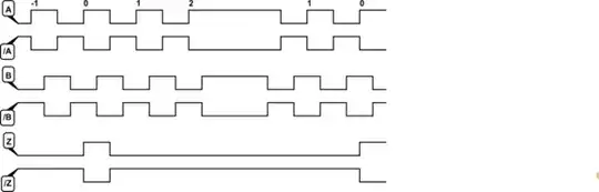
I have a sensor that has 3 components: X, Y and Z and for every component there are 2 channels:

  • X+ :0 V ± 5 V voltage output
  • X- :0 V ± 5 V voltage output inverted

All I know is :

  • If the circuit uses "active high" logic, 5 volts represents a digital "1" and 0 volts represents a digital "0".
  • If the circuit uses "active low" logic, 5 volts represents a digital "0" and 0 volts represents a digital "1".

My question is: what's the purpose of the inverted output? How can I make use of it as I am plotting results.

zx485
  • 230
  • 4
  • 9
Mehdi ouahabi
  • 23
  • 1
  • 4
  • 3
    Read about *differential signals*. – Eugene Sh. Sep 29 '16 at 16:48
  • Just had a fast look at the definition, would that mean the real value I should take on consideration is the different between the normal and inverted output ? – Mehdi ouahabi Sep 29 '16 at 16:55
  • 1
    You can very well use just one of the outputs as a single-ended, if it has a defined range relative to the common ground. The main purpose of differential signaling is to increase the noise rejection when transmitting over a long/noisy channel. If you don't have one, using them as single ended might work too. – Eugene Sh. Sep 29 '16 at 16:59
  • My reciever is a script written by me, calculating the difference between both signals would make me using the differential methode right ? – Mehdi ouahabi Sep 29 '16 at 17:10
  • Yes, the actual value is the difference. – Eugene Sh. Sep 29 '16 at 17:12

2 Answers2

2

If you are describing an encoder - not a sensor then your outputs are probably:

X+: 0 and 5V. (not ± 5 V) X-: X+ inverted.

schematic

simulate this circuit – Schematic created using CircuitLab

Figure 1. A typical A-B-Z quadrature encoder output waveform with differential outputs.

The inverted output gives the ability to improve noise immunity in the presence of electrical noise.

enter image description here

Figure 2. This diagram illustrates how a differential encoder is able to ignore noise. Channel Ā is the inverse of channel A, generated inside the encoder. However, when noise is introduced along the wire between the encoder and the encoder interface, the noise will be almost identical on both channels. Since the noise is not inverted on channel Ā, the differential encoder interface can perform a few simple operations to filter out the noise. Source: Phidgets.

Transistor
  • 168,990
  • 12
  • 186
  • 385
1

Supplementary info

Inverted Logic or "Negative Logic" is used in certain signal in many chips and legacy logic families for many reasons, and negative slope analog may be one situation you may see for all analog or digital.

But the best signal to noise ratio in signal integrity for analog and digital uses ;

differential outputs

  • eliminates sensitivity to supply tolerance
  • reduces common mode effects of vibration and electrical noise (EMI)

digital

  • 1 less inverting gate for lower latency in logic
  • Open collector drivers are faster in the active low state
  • complementary bipolar (aka TTL) is faster and has more current hi to lo
  • if low is a lower impedance state, it has better noise margin
  • for TTL inputs since Hi used less current for pullup, active Reset low
  • for power-up rising edges can be inactive thus negative edge helps some internal logic
  • and more

Analog

  • for hobby users with only single supply, negative slope transfer function allows single-ended inverting gain to create any scale for different DAC reference voltages
  • other internal reasons such as NTC or PTC temp sensors
Tony Stewart EE75
  • 1
  • 3
  • 54
  • 182