I'm looking for a simple and cheap way of creating a variable delay of up to about 2 minutes.
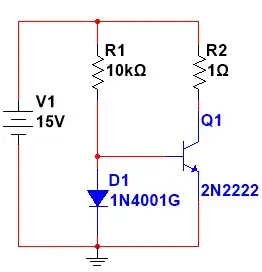
simulate this circuit – Schematic created using CircuitLab
I want to know if there's an alternative to using an RC circuit that is simple and cheap. Other concerns are secondary, within reason.
The problem with this circuit is it just seems a bit 20th century.
Firstly, the capacitor needs to be large physically because of leakage current and the small current required to turn Q3 on. This means the cost possibly leaves room for improvement. The size, weight and lifespan can probably be improved. The delay consistency can certainly be improved. (Since the capacitor's internal leakage and other leaks will vary significantly with temperature, humidity etc). Plus there's the surge when the cap gets charged.
Are there any tricks I could use? I'm wondering if there are any off-the-shelf ICs which are dirt cheap that perhaps combine a small RC circuit and some way of configuring the delay that is perhaps implemented by a binary counter.
I'm still playing around with ideas so I'm not sure what there will be in the way of power rails; if necessary I could make a 5v rail available, but it would be useful to know if there's a solution that could work on as little as 1 volt. So this question is less about solving my specific problem, but checking that I'm not oblivious to some general purpose alternatives.
[Re: duplicate: This is not a duplicate question. The answers given for the question identified as a possible duplicate offer no improvement as requested by my question. A 555 timer still uses an RC circuit without a solution for a large capacitor!]